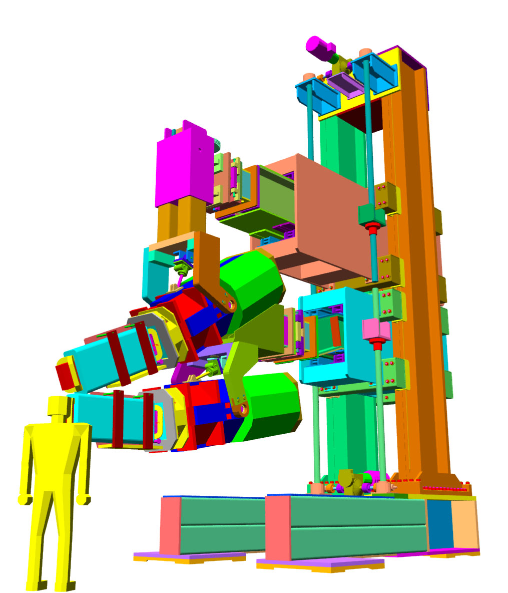
Images of the OOPS Gantry Support StructureThe basic design of the gantry is that of a cartesian robot. Each spectrometer is supported from its own independent alignment system allowing each one to be positioned in all six degrees of freedom. Motorized screw jack drives move each OOPS module vertically and horizontally, and there are manual alignment mechanisms at the ends of the upper and lower support cantilevers to align the roll, yaw, and pitch angles, and transverse position of the OOPS modules. The gantry is about three stories tall, and weighs 120 tons with its OOPSs mounted. Bartoszek Engineering, working with the Straits Company, produced over 200 manufacturing drawings for the gantry. We also assisted in shop selection and created the drawing bid packages that were used to procure the parts. Bartoszek Engineering did vendor liason to help solve manufacturing problems as they arose.
This picture shows the Gantry Support Structure. The figure of the man in the foreground is six feet tall. Both of the OOPS modules mounted on this structure are independently alignable to the target point.
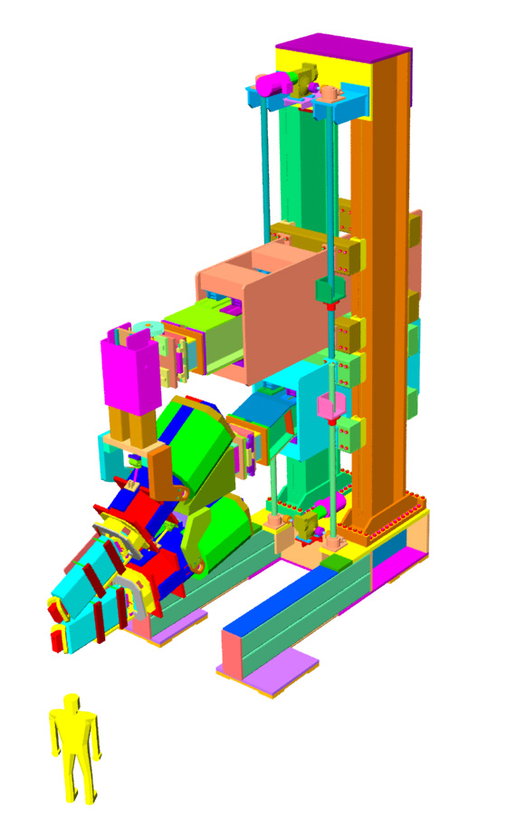
This is a view of the gantry from above without perspective (AutoCAD's DVIEW turned off).
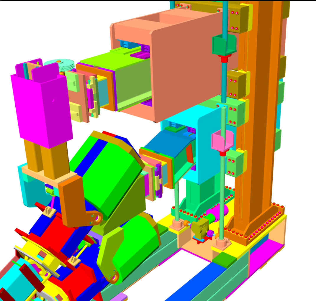
This is a detailed view of the Gantry Support Structure focusing on the alignment mechanisms at the end of the cantilevered beams.
A close-up of the lower OOPS cantilever beam and adjustment mechanisms. This view was made before the details of the air caster base and column base were finalized.
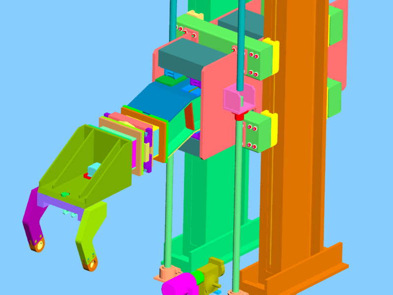
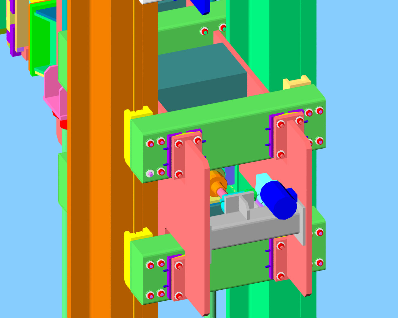
A detailed view of the lower radial and vertical adjustment mechanisms from behind the gantry. Horizontal backlash is controlled by varying the distance between two ACME nuts. ACME jack screws were chosen over ball screw jacks to save cost.
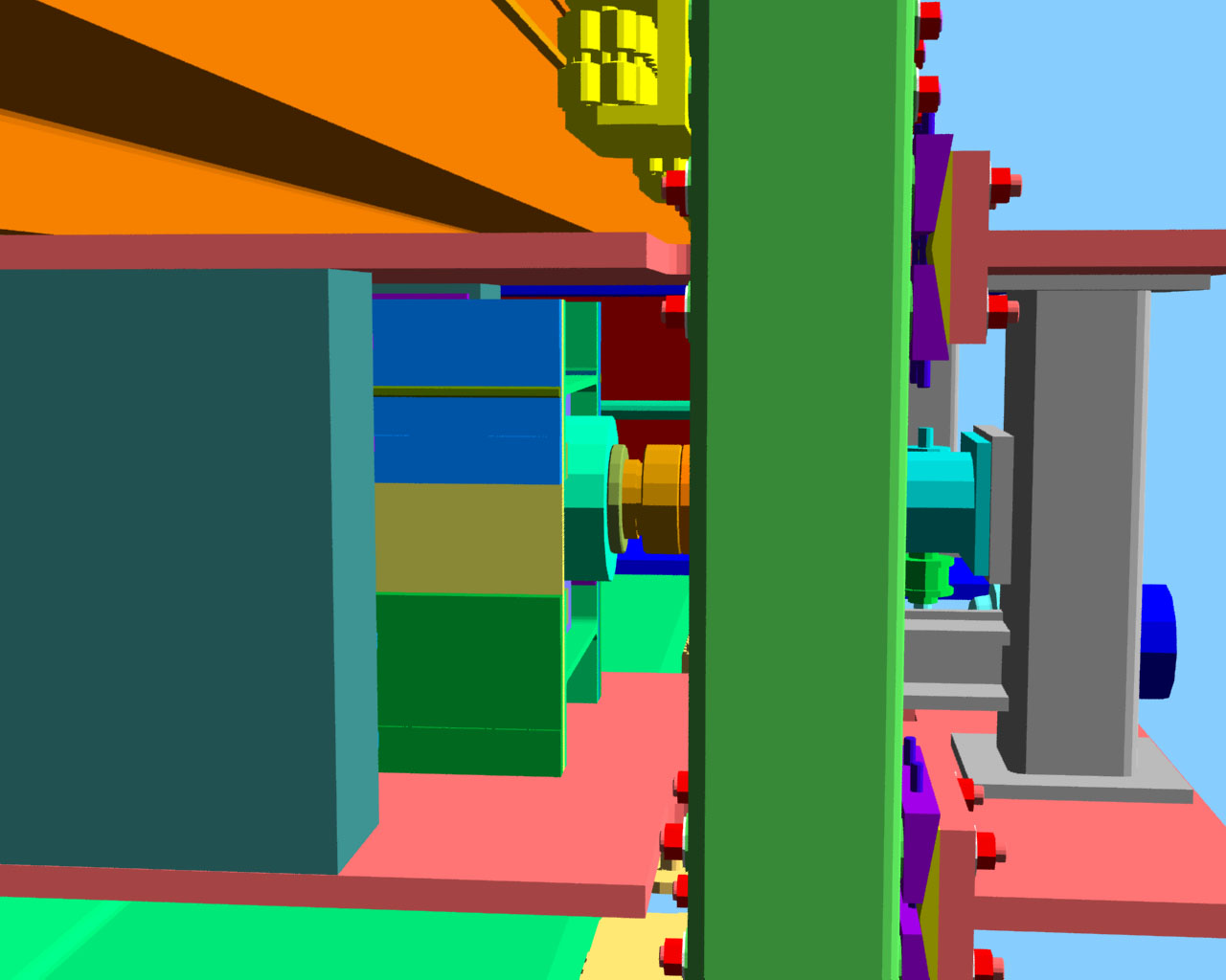
A bottom view of the lower radial mechanism to see if some nuts could be reached with tools. Understanding the access from the 2D drawings was very difficult. Solid modeling aided in determining whether this complex mechanism could be assembled.
Back to the OOPS Main Menu
Back to the Bartoszek Engineering Home Page
|