|
Conceptual Design of the First Construction Climber for the Space Elevator Work done up to 9/13
I have been working on conceptual designs for the Space Elevator as a "hobby" ever since reading Bradley Edwards' and Eric Westling's book The Space Elevator--a revolutionary Earth-to-space transportation system. In this book Edwards and Westling propose what I believe to be the cheapest method of constructing a space elevator the moment the carbon nanotube fabric becomes available. On this page I will show the papers and presentations I wrote for the Third International Space Elevator Conference (Washington, DC, June 28-30, 2004) and Space Exploration 2005, (Albuquerque, NM, April 3-6, 2005).
I have focused on the design of the first construction climber because the pilot ribbon of the space elevator presented in the book has a strict weight limit for the first climber. The idea is that the pilot ribbon is the largest ribbon that can be flown in the space shuttle cargo bay and assembled in orbit around Earth. After ribbon deployment past geosynchronous orbit and anchored on Earth, two hundred and thirty climbers climb the ribbon each adding a length of new ribbon to the pilot and increasing its load carrying capacity by 1.3%. After two years, the ribbon is capable of supporting a 20 ton climber with a 13 ton payload and it's ready for business.
My work has shown me that designing a 900 kg climber for the first construction climber is a significant design challenge. My first attempt is too heavy by almost a factor of three and is significantly hampered by lack of a commercially available axial gap motor in the 20kW and up range. The pictures shown here give conceptual solutions to some climber design problems using standard Earth-based commercially available mechanical components just as placeholders to see if the mass budget can be achieved. One of my concerns is that space-rated components might actually be larger and heavier to satisfy operation in vacuum and at extreme temperatures. The components shown are rated for the expected loads assuming that the coefficient of friction between the ribbon and climber is about 0.1.
Mathematical modeling of the climber and ribbon as a mechanical traction drive system pointed out that this currently unknown coefficient of friction completely determines the stress state of the climber. A traction drive gets traction by pinching the ribbon. The slipperyer the ribbon, the harder the climber has to pinch it to get traction. If the ribbon turns out to be too slippery, the climber may be impractical.
I taught a short course called "Moving into Space" in 2004 where we made a very informative model of the space elevator. We took a standard 12" globe of the earth, a soft-ball sized model of the moon and a piece of string. For a standard globe, the space elevator is an invisibly thin string about eight feet long extending out from the equator. Place the moon about 30 feet away from the earth to get the whole system to scale. It becomes obvious that the space elevator construction project would be the longest object ever built by humankind.
Click on any of the thumbnails to get an enlarged view. You are welcome to download any of the images. If they are used for other than private viewing, credit to Bartoszek Engineering would be appreciated.
Conceptual design similar to the one presented in the book
This picture is from the ISR website and is a tracked traction drive favored by Brad Edwards. A ribbon-pinch mechanism, motors and other systems are not shown. This is the starting point (and departure point) for my design work on the climber.
Renderings of the 2004 Solid Model of the First Construction Climber
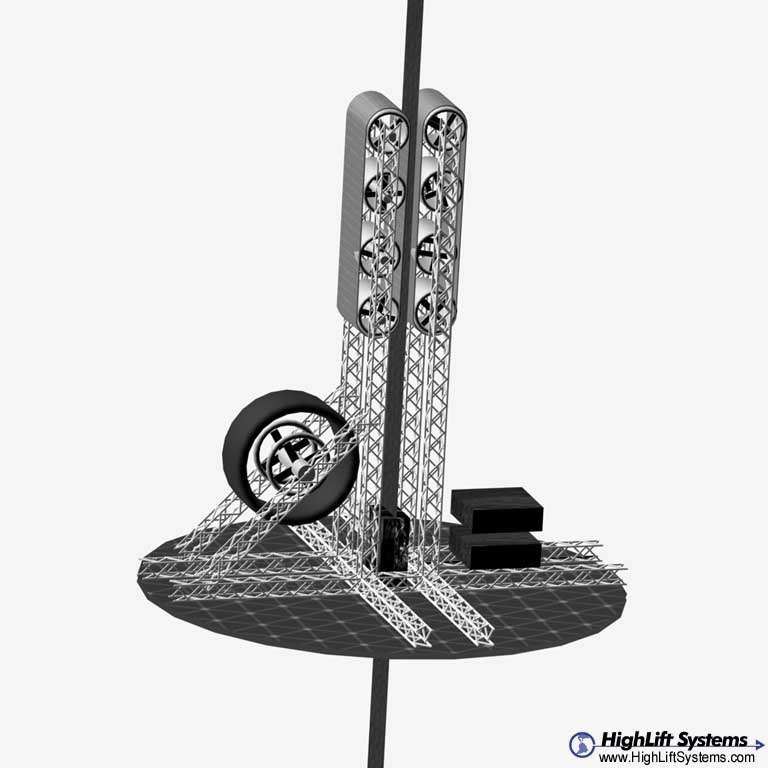
This picture shows the relative scales of the climber, ribbon and a person. The pilot ribbon is only about 6 inches wide at the anchor point on the equator. The blue circular structure is a photovoltaic array 4 meters in diameter that absorbs the laser power beamed up from Earth and converts it to the electrical current used by the motors and other climber systems. To lower the current, the PV array must provide power at ~2500 volts. The ribbon poses unique assembly challenges for the climber because it is effectively an object with no access to either end. (The anchor-end at earth is wrapped around a drum with a complex drive system to maintain ribbon stress and counterweight altititude. The other end is 100,000 km up.) The climber must therefore be assembled in halves on opposite sides of the ribbon.
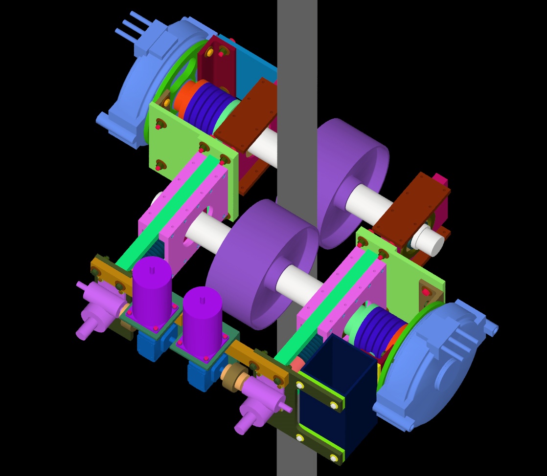
The traction drive is made up of two different modules on opposite sides of the ribbon. Each has a motorized wheel, but the wheel on one side of the ribbon is free to move perpendicular to the ribbon. The module on the opposite side holds the wheel fixed. A screw jack drive pushing against springs forces the floating wheel against the fixed wheel to pinch the ribbon hard enough to get traction.
The individual modules are not rotationally stable without a fixed structure connecting the two bearing housings on opposite sides of the wheel. The fixed structures connect traction pairs to each other and to the rest of the climber structure. This design attempts to put material only between the objects to be supported and the ribbon (the load path to the ribbon).
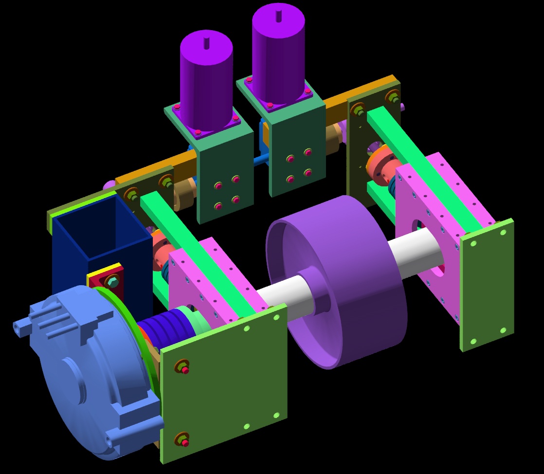
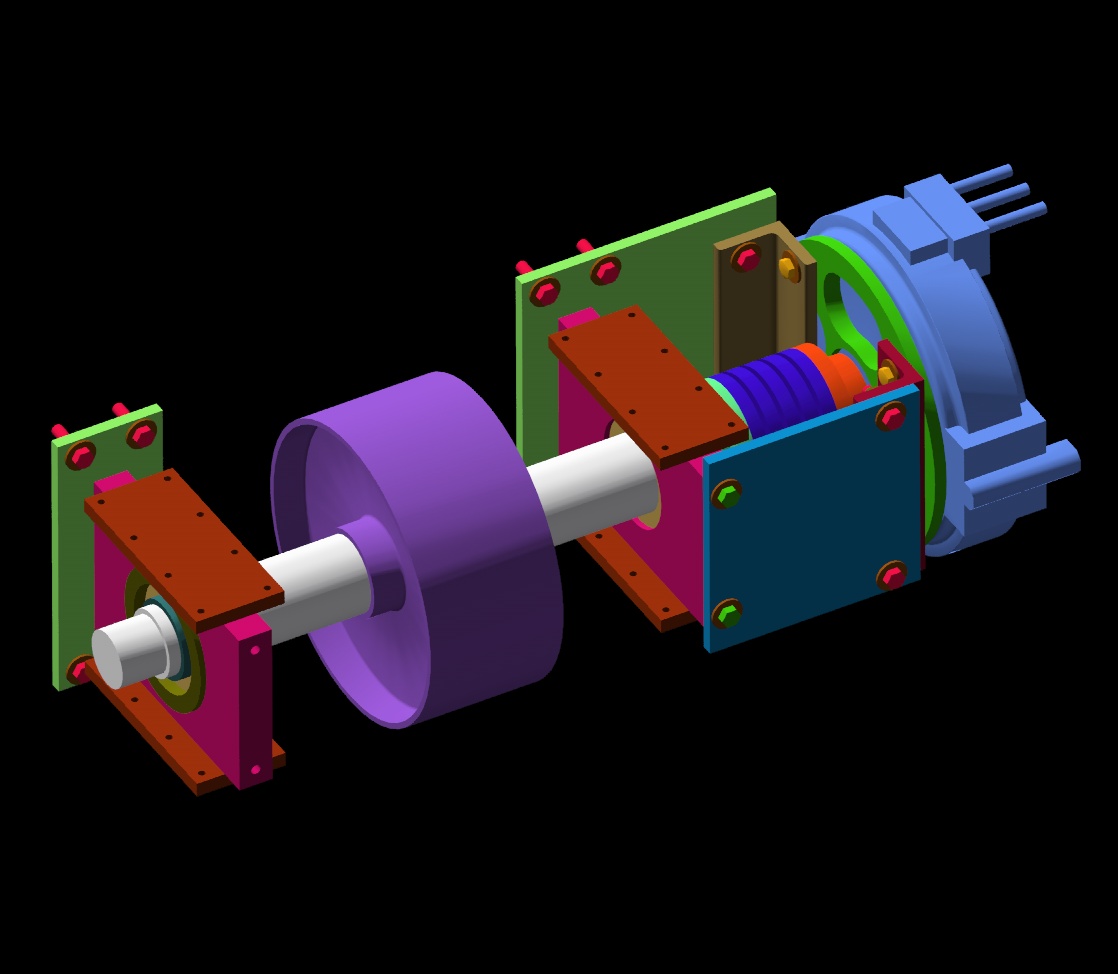
This view shows the floating axle module by itself.
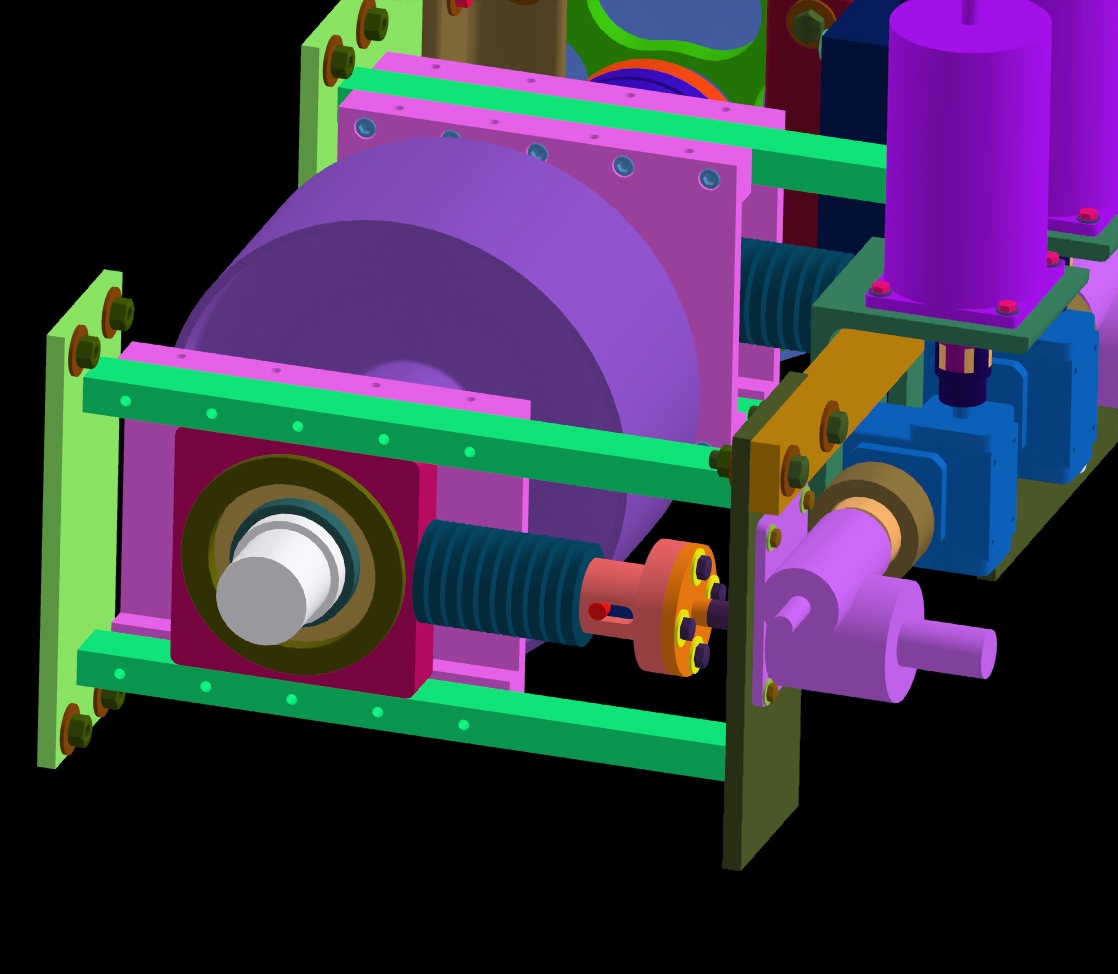
This picture shows the detail of the compression mechanism that forces the floating wheel against the fixed wheel. The bearings which allow the axle to rotate in the floating module are mounted in blocks that can slide on the climber structure. The blocks are pushed on by belleville spring stacks loaded by a screw jack. The reason for putting the spring in the mechanism is to spread out the distance over which the compression force is applied. This increases the resolution of the compression mechanism allowing for fine adjustments of force to the ribbon. As the climber increases in altitude up the ribbon, the force of gravity diminishes so the pinch force can be decreased.
One feature of the design is that different forces can be applied on opposite sides of the wheel. This is a potential mechanism for correcting sideways drift of the climber. As differential forces are applied, the wheel will take a conical shape which will force it to move sideways as it rolls. This will require an active feedback loop on the position of the climber on the ribbon.
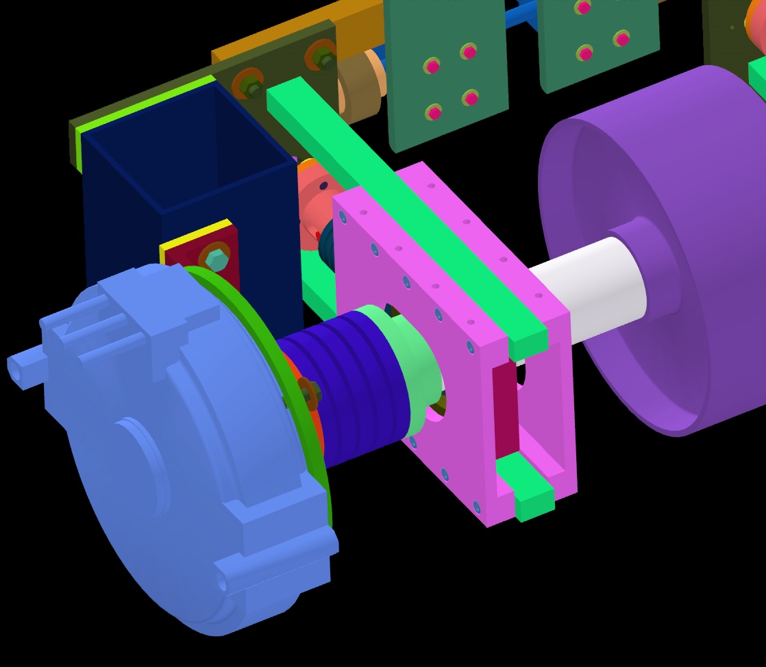
This view turns off the plate that bolts one module to another to expose the coupling between the motor and shaft. The axial gap motor shown in this design was provided as a CAD model from Dantam Rao of Precision Magnetic Bearings. I think it represents a 50kW axial gap motor designed by PMB for electric vehicle applications, but as far as I know this motor is not available commercially. It is used as a reasonable place-holder for the actual motor. In this design, the motor is fixed to the climber structure, but the floating axles move with respect to the motor shaft. The solution shown here is a Schmidt coupling which can connect fixed motor shafts to moveable driven shafts without applyng a side load to the motor shaft.
This is a view of the fixed axle module. The wheel/axle is not moveable with respect to the motor shaft in this module and provides reaction to the force pushing on the floating wheel/axle on the other side of the ribbon. (It is of course, free to rotate and driven by its motor.)
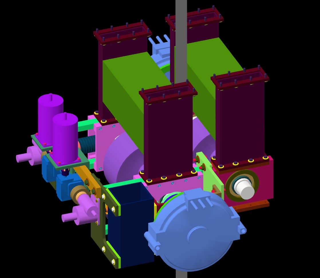
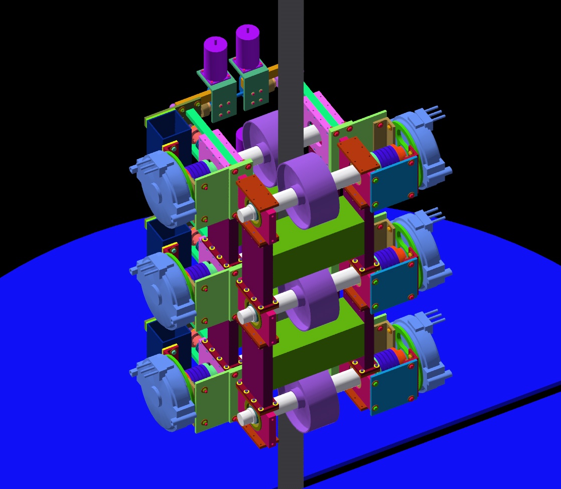
This is a close-up of the assembled climber with three floating modules, three fixed modules, and four connecting interface structure modules. Allowance is made in the design to absorb manufacturing tolerance errors in bolted connections. Much work needs to be done to lighten the structure to satisfy the mass budget.
Calculations
Link to a MathCAD document, in PDF format, on the power requirements of a climber under conditions of constant velocity, constant acceleration, and the acceleration allowed by the safety factor of the ribbon.
Presentation from the Third International Space Elevator Conference, Washington, DC, June 28-30, 2004
Presentation from Space Exploration 2005, Albuquerque, NM, April 3-6, 2005
Colloquium presentation given at Fermilab and NMSU, 11/2005
Presentation from the International Space Elevator Conference, Seattle, WA, August 23-25, 2013
Back to the Bartoszek Engineering Projects Page
Back to the Bartoszek Engineering Home Page
|