Photos of the Thyratron Power Supplies Larry Bartoszek worked on at FermilabThe photos on this page show the pulse forming networks and thyratron switching systems Larry Bartoszek worked on during the very early days of the Antiproton Source at Fermilab. These systems create the pulse of current that becomes the "kick" in each of the kicker magnets in the Source. (See the Shuttered Injection Kicker Page for a description of the kickers.) A conventional power supply charges a length of RG220 coax cable wound onto a spool such that it acts as a long capacitor. The length of the cable determines the pulse length of the signal, about 100 microseconds long for shuttered kickers. The cables are all connected to very fast hydrogen thyratron switches. When these switches turn "on", the energy stored in the cables is shunted through to the kicher magnet down in the tunnel. Because the signal develops a "tail" as the cable discharges, a second thyratron fires at the end of the pulse grounding the cables and "clipping" the energy pulse to have a very short fall time. After coursing through the kicker magnet, the pulse of energy is then returned up to the service building through more cables and dumped into a resistor. The very fast rise and fall times of the pulse in this system create the need to impedance match every component in the system as well as possible to avoid "ringing". Much attention was paid to the design of connections between the cables and the thyratrons, and in creating a coaxial ground shell around the thyratrons themselves to match them to the cables. Larry Bartoszek was responsible for all the mechanical design and installation of these systems, Tim Castellano and Jeff Petter were responsible for the electrical design. Some photos are courtesy of Fermilab Media Services. (Presentation of photos from Fermilab does not imply endorsement of any product or service.) You are welcome to download any of the images. If they are used for other than private viewing, credit to Bartoszek Engineering and Fermilab would be appreciated.
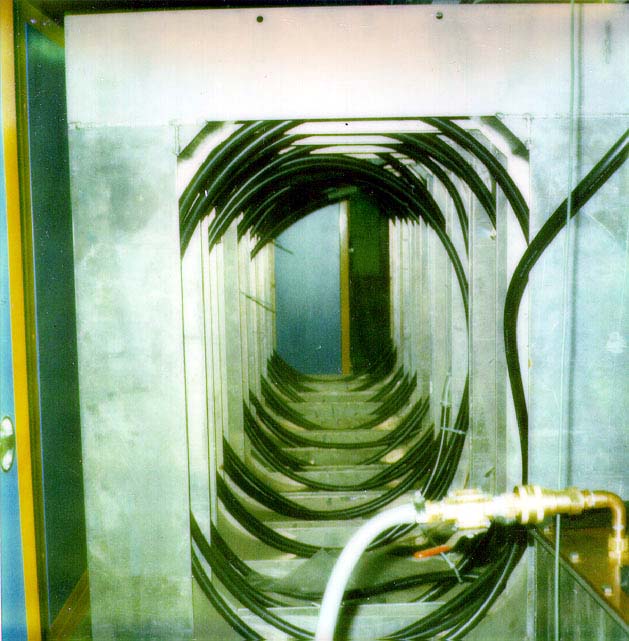
This picture was taken through the centers of a set of spools of RG220 cable which act as a pulse-forming network. The spools are approximately six feet high and were wound by hand with a crank device that attached to a forklift and allowed the spool to be lifted and rotated. Larry Bartoszek designed the spool cranking device which was a great improvement over the previous method of driving a golf cart around a spool to wind the cable onto it.
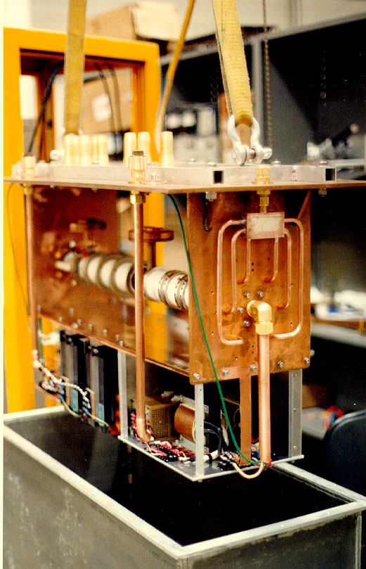
Hydrogen thyratron switches are plasma devices that conduct electricity through a ceramic tube filled with hydrogen gas that is ionized to make it conductive. They run quite hot and must be cooled in an oil bath. The copper plumbing shown was part of a system originally intended to flow oil around the tubes, but this system was balky and later found to be unnecessary.
The only thing missing from this assembly is a copper and nested G-10 tube structure that was assembled around the thyratron tubes. This copper sheath acts as the gound plane and coaxial shield for the thyratrons. The thyratron tube on the right is the clip tube which shorts the tail end of the pulse to ground. The one on the left conducts current from the center cable connection (coming from the PFN) to the left cable connection going to the kicker magnet.
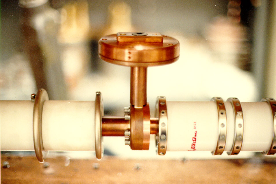
This picture shows a typical cable launcher we developed to connect groups of RG220 cables to the thyratron switches. The outer sheath of the RG220 is grounded to the outside of the thyratron box lid, and the center conductor is passed through to the top round copper plate where it is set-screwed in place. The copper sheath around the thyratrons has spun-pulled extrusions so that it wraps around the outside of the launcher and carries the ground from the lid. The launcher is made of two round copper plates allowing a multi-cable assembly to be disconnected by the loosening of the single flat head screw at the top of the top copper plate.
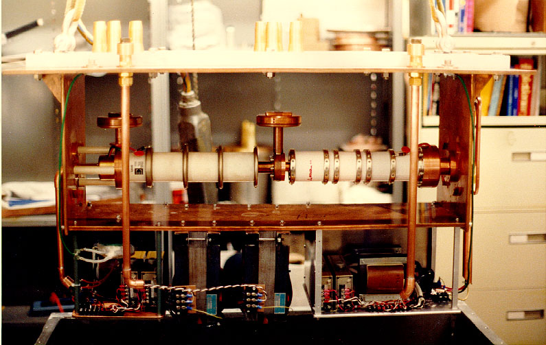
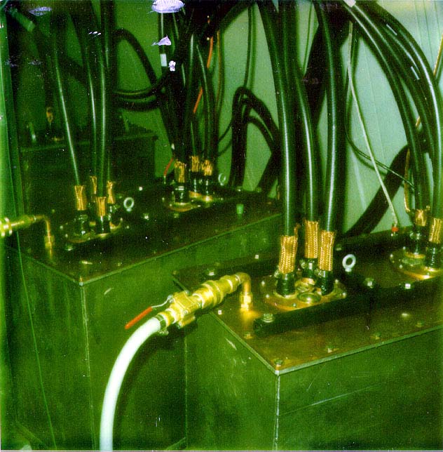
These shorter boxes show what the final assembly in the AP service buildings looked like. They are shorter than in the previous views because there is no clip thyratron tube in these systems. The clip tube was there to prevent the pulse tail from disturbing the stack of antiprotons in the Accumulator as the shutter in the shuttered kickers opened. (See the Shuttered Kicker page.) The Debuncher has no stored beam so there is no need to add more expensive hydrogen thyratrons to its systems.
Back to the Projects Main Menu
Back to the People Main Menu
Back to the Bartoszek Engineering Home Page
|