The Final Welding of the Inner ConductorThis page documents the complete process of welding the two tube welds of the horn MH1 Inner Conductor. One of the reasons for presenting the details of this process is to show how many resources in people and time are required to successfully weld the inner conductor together. Much thanks goes to all of the dedicated people at Fermilab and among the contractors to MiniBooNE that participated in this process. Click on any of the thumbnails to get an enlarged view. You are welcome to download any of the images. If they are used for other than private viewing, credit to Bartoszek Engineering would be appreciated.
The Large Diameter Weld:Scraping the joint for the sample weld on the reject IC
After many small samples were welded and X-rayed, we discovered that the simplest and most reliable means of cleaning and preparing the weld surfaces was carefully mechanically scraping the aluminum oxide layer off with a sharp steel tool. Before each final weld on the IC, we always ran a sample weld to make sure the machine was working correctly.
Making the sample weld on the reject IC
These pictures show the weld between the rejected upstream inner conductor piece and a weld sample tube to qualify the weld parameters and make sure the welding machine was working normally. This weld turned out perfectly.
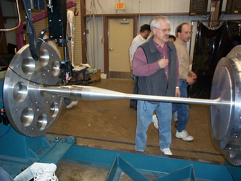
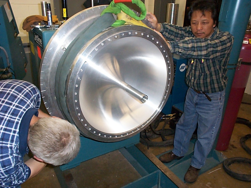
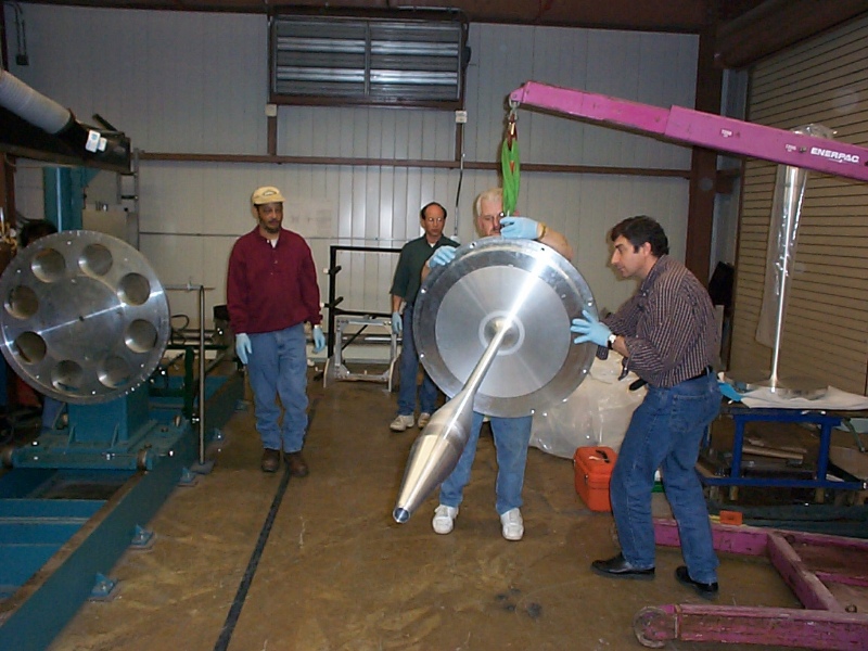
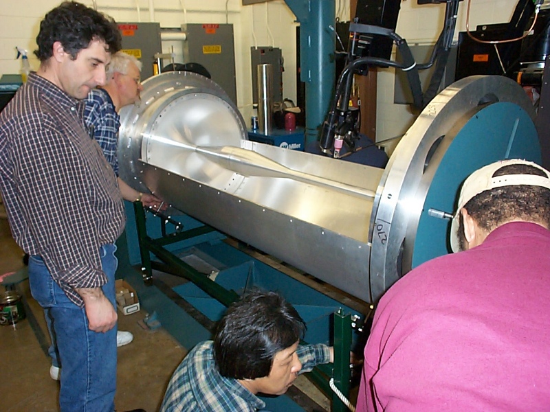
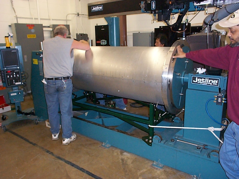
Lift-handling the final IC onto the welding machine
Fortunately, the center of mass of the upstream IC piece is very close to the upstream flange making it very easy to handle without inducing stress in the small diameter tube that sticks out. The upstream piece is manually lifted into the upstream weld fixture flange and bolted in place from behind.
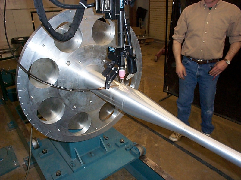
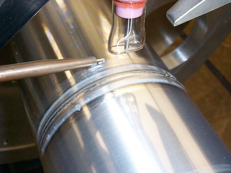
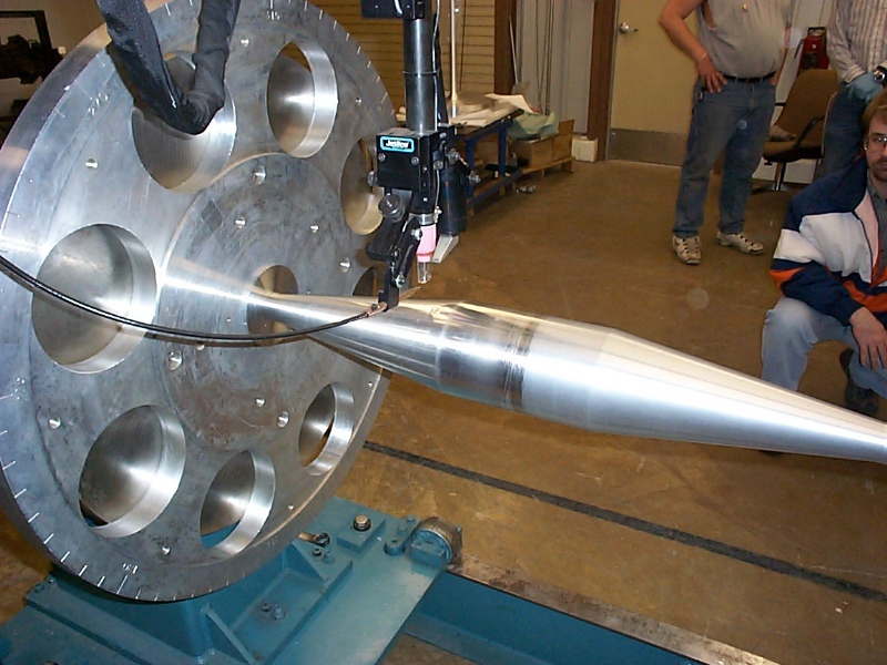
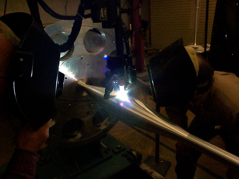
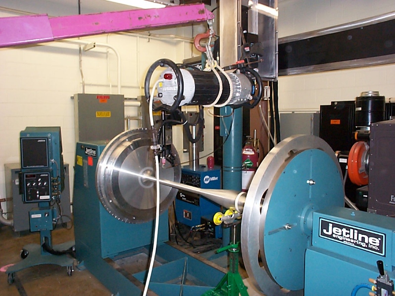
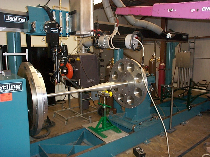
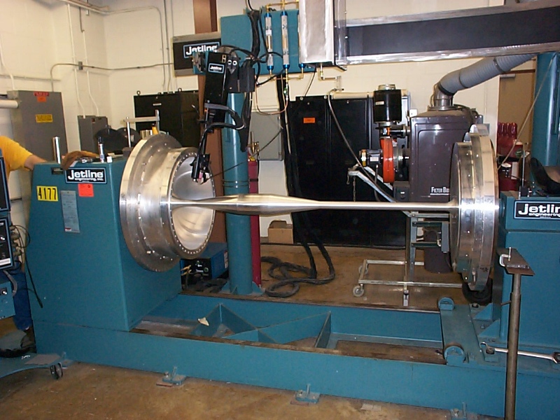
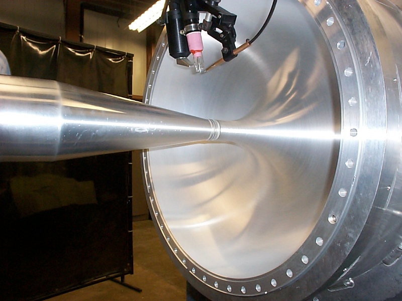
Making the large diameter weld on the final IC
These pictures show the configuration of the welding torch and head-stock and tail-stock fixturing. The last picture showing the welding arc is darker because of the automatic filtering protecting the digital camera. We did not change the room lighting. An FNAL welder always observed the arc to make sure nothing unforeseen happened. This weld took place on 3/29/01. After doing this weld we did a straightening pass on the weld to lower the runout of the total part. Straightening is done by a lower current pass from the welding torch that just begins to melt the surface of the weld. This surface melting causes metal contraction that when applied on the correct side of a non-straight part can cause the part to straighten out.
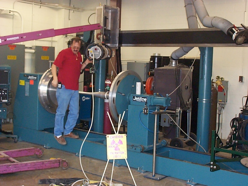
X-raying the large diameter weld on the final IC
The large diameter weld is X-rayed by a camera hanging from the lift, with the film right under the weld. (I didn't get a shot of the film. We used two of the roller blade fixtures to support the film.) The film showed no flaws in the large diameter weld at all. X-raying happened on 4/2/01.
The Small Diameter Weld:Sample weld on the reject end cap
We welded the last weld on the IC on 4/6/01. To qualify the welding machine and parameters we started by welding a sample tube to a rejected end cap.
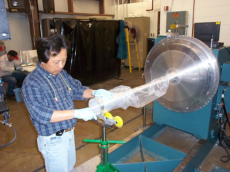
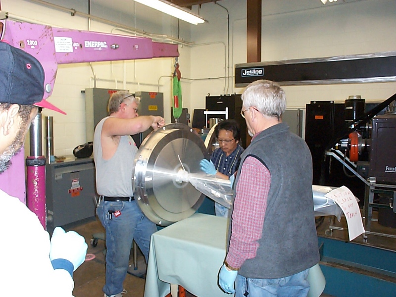
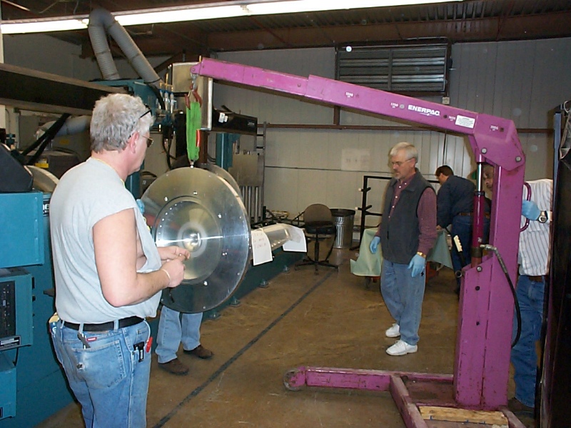
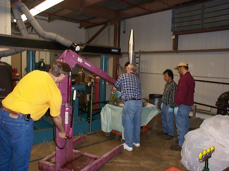
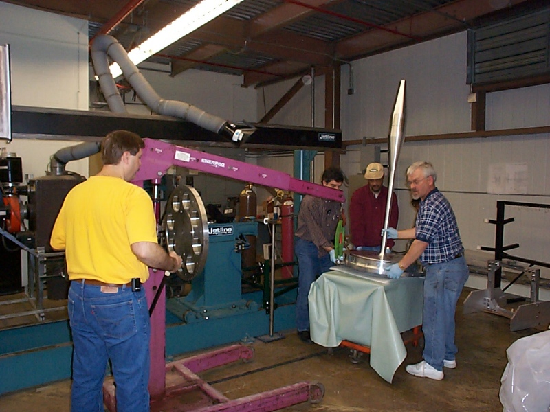
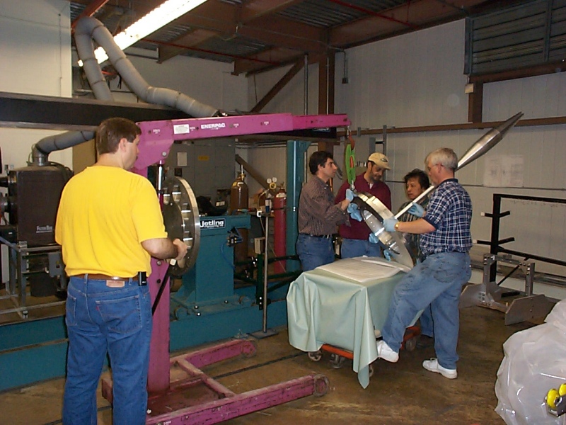
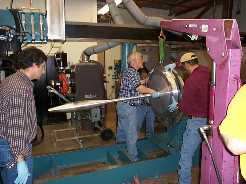
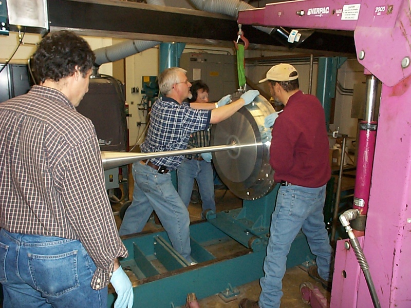
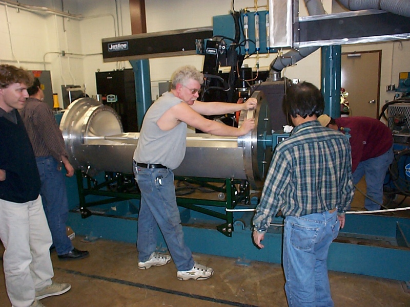
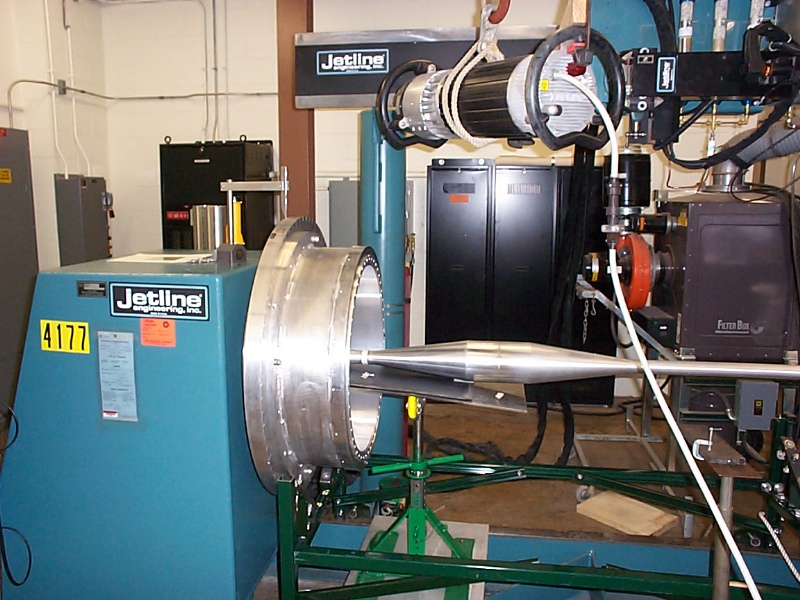
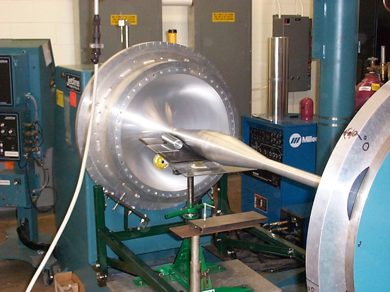
Crane-handling the upstream IC part back onto the welding machine
This sequence of pictures shows how we took the final upstream welded piece from vertical to horizontal. The CG is still fairly close to the upstream flange. At no point do we want to put the IC tube in bending.
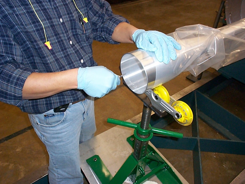
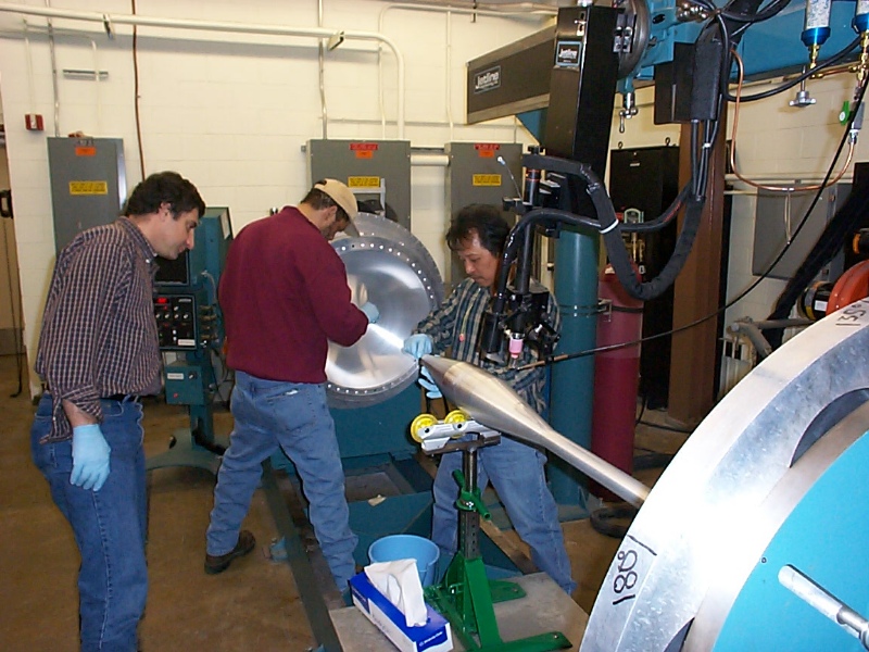
Scraping the small diameter weld
Two views of the process of scraping the weld joint regions. We used two people simultaneously because it takes about 20 minutes to thoroughly scrape each piece of the joint.
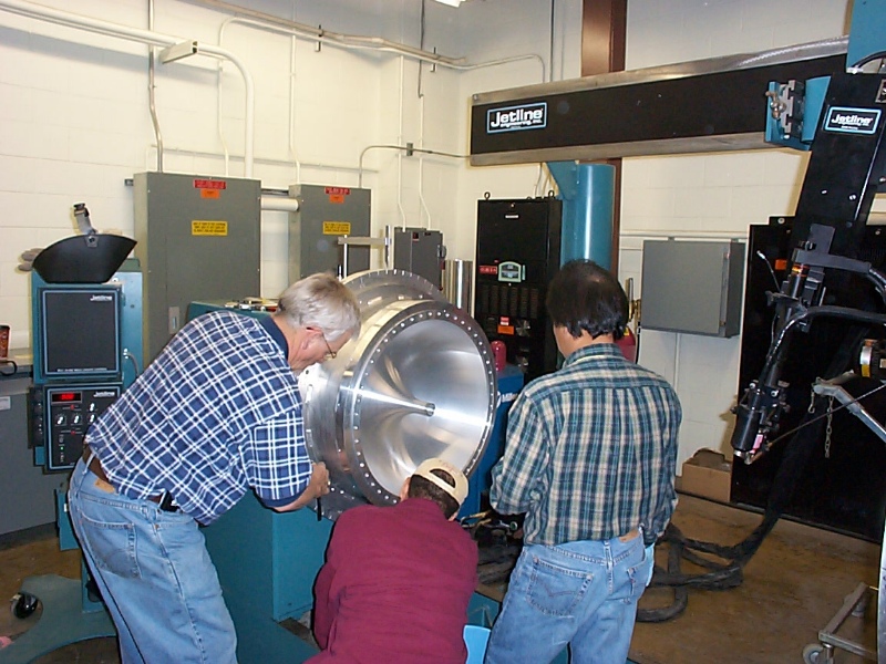
Aligning the two halves of the inner conductor
This was the first time in the process that a relationship has to be created between the two halves of the inner conductor prior to welding. We need the bolt hole patterns on the welding fixture to line up from end to end or we cannot attach the two half cylindrical shells ("clam shells") to the weld fixture which stiffens it enough to rotate the whole assembly without stressing the inner conductor. Once we bolt the downstream end of the inner conductor to the downstream end of the outer conductor, we will need to measure the angle between the bolt patterns at the upstream end of the IC and OC. This allows us to cut the bolt pattern on the upstream flange that connects the outer conductor and inner conductor.
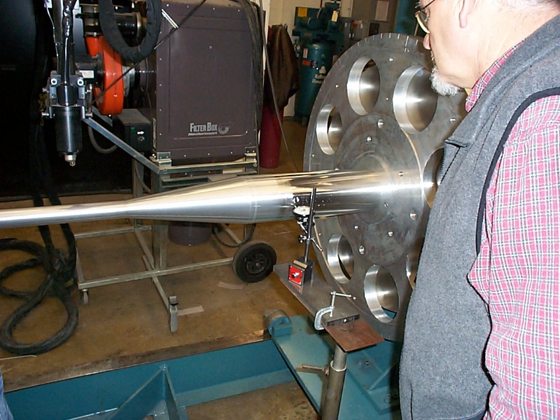
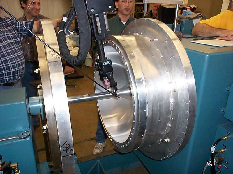
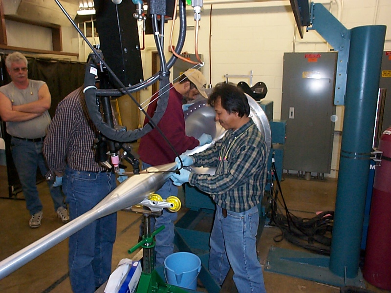
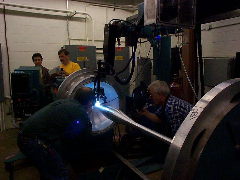
Making the last weld on the inner conductor
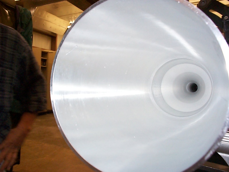
We discovered at this point that the geometry of the real weld is just enough different from the samples we ran that the weld parameters were not exactly right. The weld was too cold on the end of the joint to completely penetrate through the tube for about a centimeter at the end of the circumference. Another thing we learned is that by pulling the cover off the head-stock and feeding a borescope through the spindle we were not able to tell conclusively whether the weld had achieved 100% penetration. As shown in the following pictures, we were forced to separate the welding fixture from the head stock to get a direct look into the center of the downstream end cap.
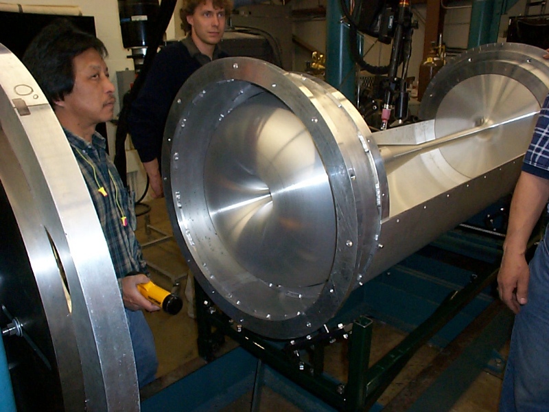
Pulling the IC away from the head stock to get a closer look at the penetration
The unistrut carriage that BE designed to hold the weld fixture after it was separated from the head and tail stock was essential for this next unanticipated step. We roped the carriage to the tail stock to insure that it wouldn't move relative to the tail stock, and we rolled the weld fixture away from the head stock to get a good look at the last weld. Direct examination showed that we had not achieved the required 100% penetration. At this point we decided to manually repair the weld because it would have taken far too long and required many expensive samples to create the weld parameters necessary to use the automatic welder to fix the weld. The last picture in this set shows the clam shells and shows that they can be assembled incorrectly such that the bolt holes along the sides do not line up. This is a point to remember for the future.
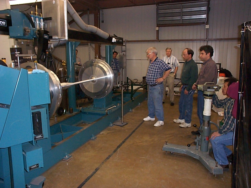
X-raying the small diameter weld
During X-raying of the weld no one is allowed in the room near the X-ray tube, so we chilled out outside the welding room garage door. The other pictures show the configuration of the camera and film for imaging the small diameter weld. Even though there is a non-uniform wall thickness at the weld, the film showed no porosity, inclusions or any other serious flaw. We will do a straightening pass on 4/12/01 and after that we are ready to assemble the horn!!! Back to the MiniBooNE Horn Main Menu Back to the Bartoszek Engineering Home Page |