Steps in moving the G0 Spectrometer out of the NPL Barn at UIUCPosted 1/5/02 Last update 1/23/02
The pictures that follow present one possible method of crane handling the G0 spectrometer in the NPL barn at UIUC as part of the process of moving the spectrometer from UIUC to Jefferson Lab. The rigging company selected for the job has the responsibility of putting together the equipment and plan for the movement of the spectrometer, but this document is intended to make clear the lifting points on the spectrometer and the motions necessary to get the cryostat out of the roll up door at NPL. Comments on the scenario presented are welcome. For details of the shipping fixture attached to the spectrometer, see the "Design of the G0 Cryostat Shipping Fixture page."
Not all of the rigging hardware is shown in these pictures. Some small pieces have yet to be designed, and are subject to negotiation with the company that is selected for the job. The places that the lifting lines are connected to on the cryostat are the pick points on the cryostat, it is just the actual shackles, swivel hoist rings, etc which are not shown. No attachment of the lifting lines to the jacking tower beams is shown as that is at the discretion of the rigging company (as is the nature and type of the lifting equipment).
The lifting lines themselves were drawn as an envelope of 2" diameter wire rope for simplicity, and to make sure the lines would render in the views. The actual rigging hardware is entirely up to the rigging company. Chains, slings and wire rope of the appropriate capacity are all acceptable rigging supplies. No connecting rings or shackles are shown.
The red lines in the floor of the building are steel plates that were embedded into the floor many years ago for the building's previous usage. They are not completely flush with the floor and the concrete has been spalled in places along the path of the cryostat where it has been overloaded previously.
Click on any of the thumbnails to get an enlarged view. You are welcome to download any of the images. If they are used for other than private viewing, credit to Bartoszek Engineering would be appreciated.
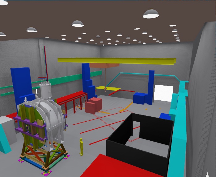
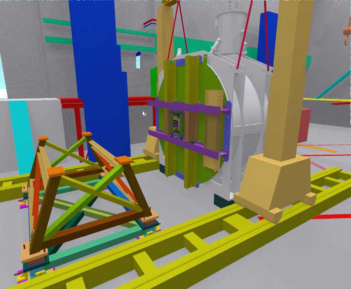
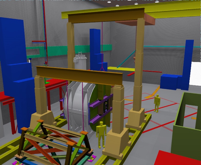
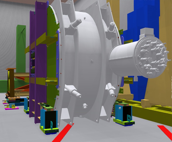
Step 1: The cryostat on its support stand with the shipping fixture assembled
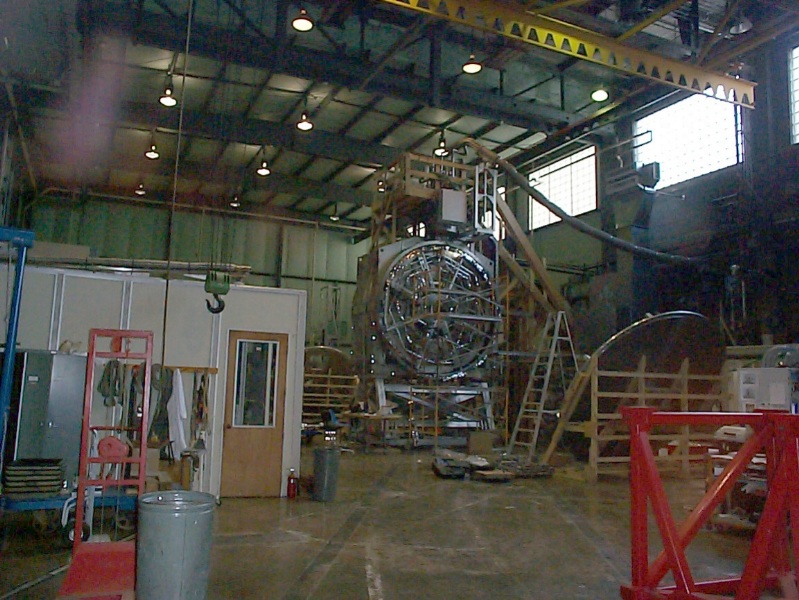
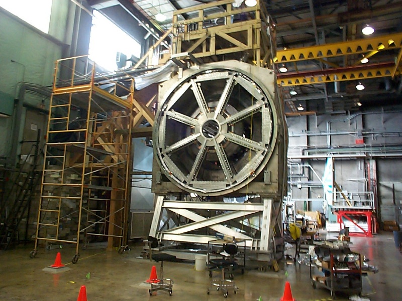
The first picture is the state of the G0 cryostat as it will be just prior to movement by the rigging company. The shipping/transport fixture will be assembled by NPL technicians. The second two photos were taken inside the barn on 1/18/02 and show the status as of that date. The middle photo was taken standing near the roll-up door that the cryostat will leave the barn through. The right photo is a similar view to the left, but taken from floor level. You can just see the roll-up door on the far right of this photo.
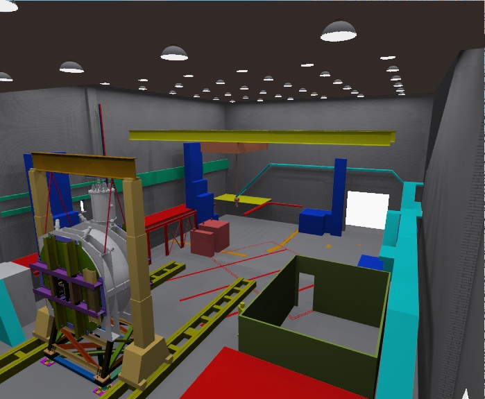
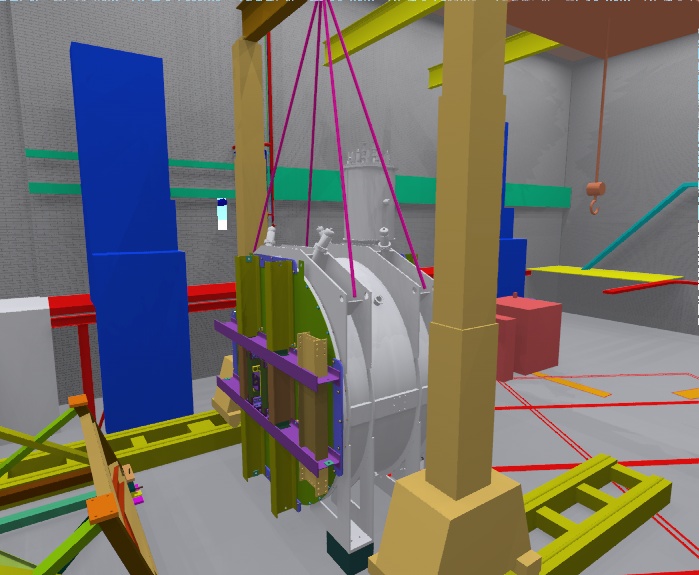
Step 2: Lifting the Cryostat off the stand
This scenario assumes that the rigging company will use hydraulic jacking towers that are mounted on portable tracks that allow the towers to be moved (also hydraulically) along the tracks. This equipment is not a requirement of the job. The cryostat has been moved with mobile cranes before. From experience, if mobile cranes are the chosen method, then two 80 ton cranes are recommended over other combinations of capacity.
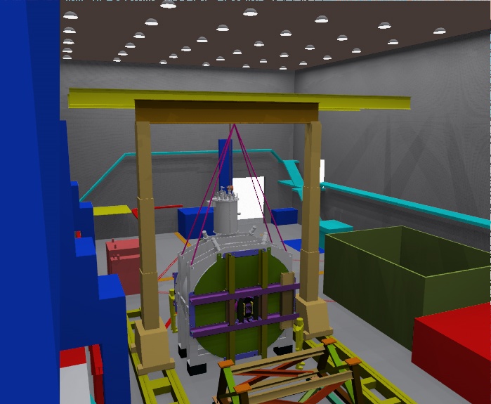
Step 3: Translating the Cryostat away from the stand
One advantage of the jacking tower scenario is the ability to translate the cryostat horizontally on the tracks after it has been lifted. This makes clearing the stand easier than in the scenario where cranes lift the cryostat and the stand has to be rolled out from under the cryostat (as was done in the previous move.)
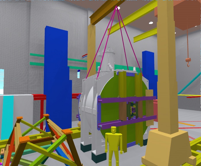
Step 4: Setting the Cryostat on risers on the floor to prepare for re-rigging
The cryostat must be supported on risers (steel ones are available at NPL, but timbers may be used as well) to prevent the flanges and tube stubs under the cryostat from being crushed, and because the feet of the cryostat are slightly above the bottom of the cylindrical vessel. Once the cryostat is on the floor, the jacking towers can be reconfigured for the next movement.
Step 5: Rigging for Yaw Rotation of the Cryostat
These pictures show the next rigging configuration. Not shown is a necessary swivel between the lines and the jacking tower cross beam that will allow us to spin the cryostat about a vertical axis.
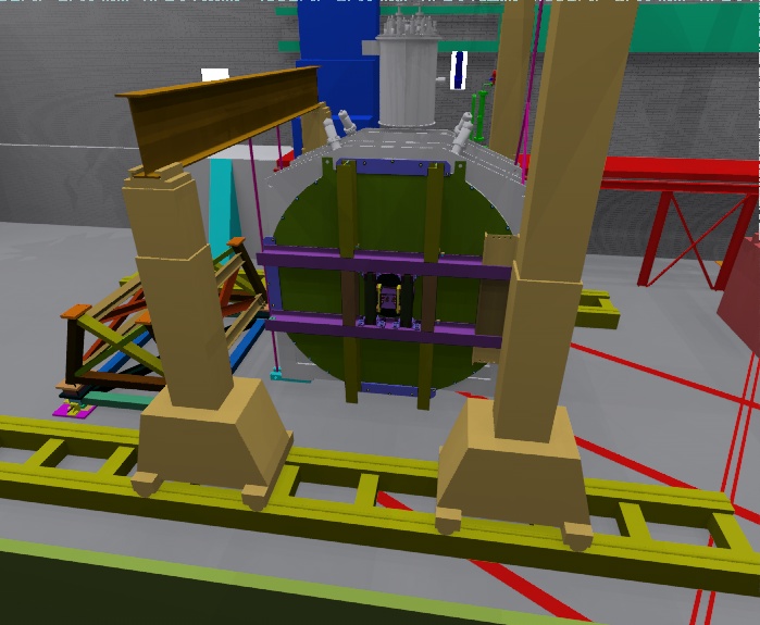
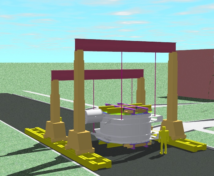
Step 6: Rotating the Cryostat in Yaw
This picture shows the final configuration of the cryostat after it is yawed about a vertical axis.
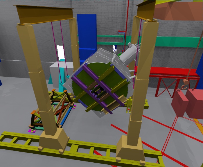
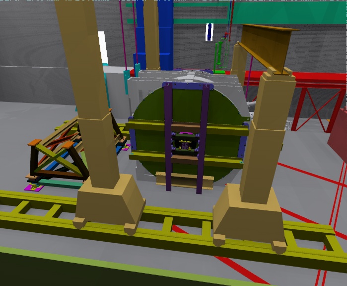
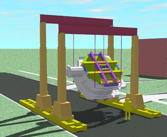
Step 7: Pitching the Cryostat about its beam axis
The can on top of the cryostat (the "cryoreservoir") is too tall to make it through the door at NPL or at JLab in its normal vertical orientation. The cryostat must be rotated around its beam axis to lower the overall height of the device. This is accomplished here by assembling two more jacking towers, raising one pair and lowering the other pair. Care must be taken to rig in such a way that the cryoreservoir is not touched by any rigging lines during the rotation. The cryostat is again lowered onto thin plates of the right height to allow the legs in the next step to be assembled.
Step 8: Assembling the feet of the transport fixture
These attachments to the shipping fixture allow the cryostat to be rolled across the floor at NPL, and down the truck ramp at JLab. They are attached with a bolted moment splice to beams welded to the shipping fixture. The feet are designed to accept different models of rollers in a reasonable range of sizes, and are pivoted for transitioning up and down ramps.
Step 9: Translating the Cryostat to the door of NPL
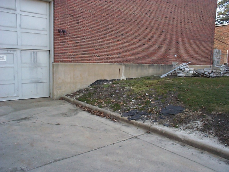
This is like a time lapse image of the cryostat rolling across the floor toward the roll-up door at NPL. It is obvious that yaw adjustments will have to be made to the assembly as it progresses toward the door. These yaw adjustments will require the ability to apply large horizontal forces to the cryostat, and probably some reconfiguring of the rollers. The clearance between the top of the door and the top of the cryostat is less than 1 inch with the bottom of the cryostat 3/4" off the floor. There is also a 2" discontinuity right at the door where the barn floor is 2 inches higher than the driveway outside.
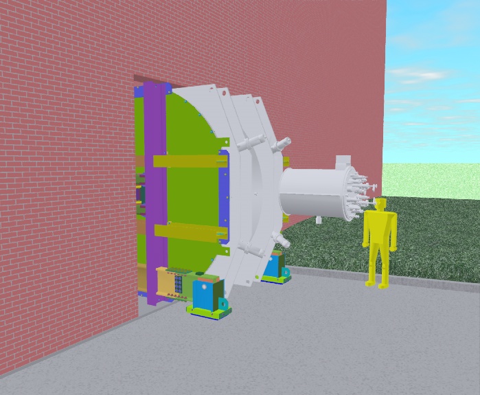
Step 10: Emerging into the sunlight
This picture shows the tight fit of the spectrometer through the roll up door at NPL, and the 2 inch offset between the interior floor and the driveway. Steel plates will have to be laid down to bridge the discontinuities.
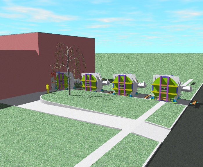
Step 11: Translating from the doorway to the curb
This is another "time lapse" image of the spectrometer moving along the driveway to the street. The topography of the area immediately outside the barn door is too complex and tight to erect the hydraulic jacking towers in. It is possible to place two mobile cranes in this area, as that was done last year when the spectrometer was brought to NPL. I render the following concept to see if the entire job could be done without mobile cranes doing all of the steps with the hydraulic jacking towers. One idea that was suggested was to do the rotation of the spectrometer over the sidewalk. This had the advantage of not blocking the street, and we first thought that the terrain was more favorable to the jacking towers. Upon setting up that scenario it became clear that it was not the most efficient way to do the job. See the following renderings.
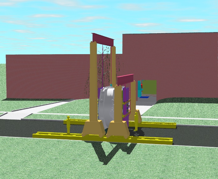
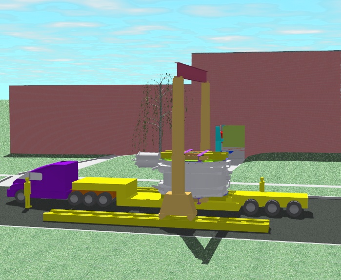
Step 12: Rotating the beam axis vertical
These images show the setup required to take the spectrometer from its rolling configuration to beam axis vertical so that it can be placed on a "low boy" flat bed truck. If we had set up this rotation at the sidewalk, the yellow portable tracks would have been north and south of the spectrometer. (The axis from the roll-up door of the NPL barn along the driveway points north. Stadium drive, the street in view is an east-west street.) This would have allowed us to rotate the spectrometer to the desired orientation, however, the spectrometer would have to be lowered down to cribbing, the jacking towers disassembled and then the tracks repositioned on either side of the driveway to allow a truck to back under the spectrometer. The ground beneath the portable tracks would vary from soil to concrete sidewalk to asphalt, with shimming necessary to make up large differences in elevation.
It seemed much more efficient to simply block off the street, set up the tracks on either side of the street, and do the final rotations in the street. Once the spectrometer is made horizontal and lowered onto cribbing, a yaw rotation is made rigging the spectrometer similarly to what is shown in steps 5 and 6, but with the cylindrical axis vertical. (See the next step.)
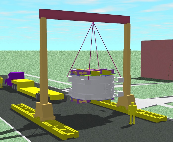
On 1/18/02 I went to UIUC to check some measurements. The width of the Stadium drive assumed when these pictures were rendered was 32 feet. In actuality, Stadium drive is 41 feet wide, so there should be plenty of room for this configuration in the street. Step 13: The last yaw rotation and lowering the spectrometer onto the truck
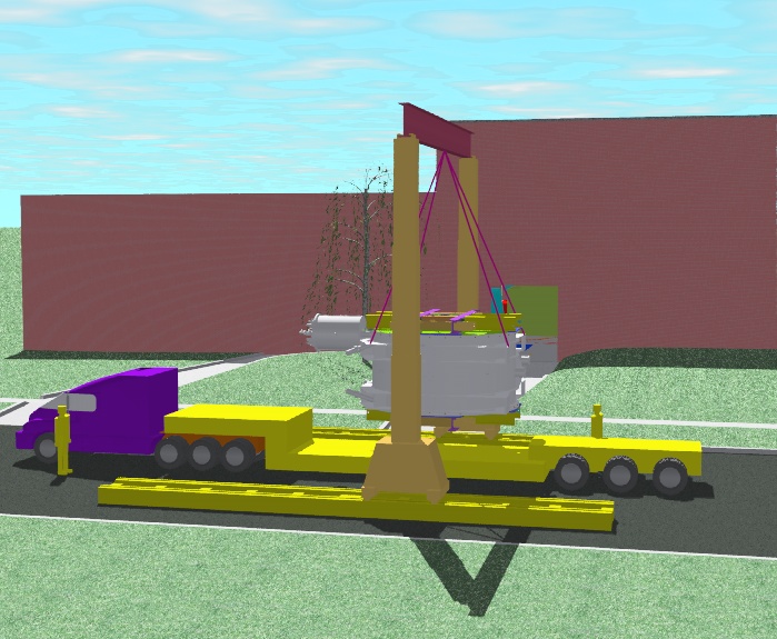
The width of the street has been increased here to reflect the measured 41 foot width. These pictures show how the last yaw rotation would point the can on top of the spectrometer parallel to Stadium drive, the orientation necessary to mount the spectrometer on a truck. Setting up this rotation showed me that the tracks have to be spread even farther apart for this rotation so the feet of the spectrometer do not interfere with the jacking towers. The length of the beam on top of the towers in this view is 31 feet. At several points in the development of this sequence I was forced to move the tracks farther apart and lengthen the beams between towers. I have not gone back and checked to see whether the longest beam will work inside the NPL barn, but this can be done by request. Any dimensions for any configuration can be made available upon request.
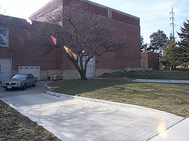
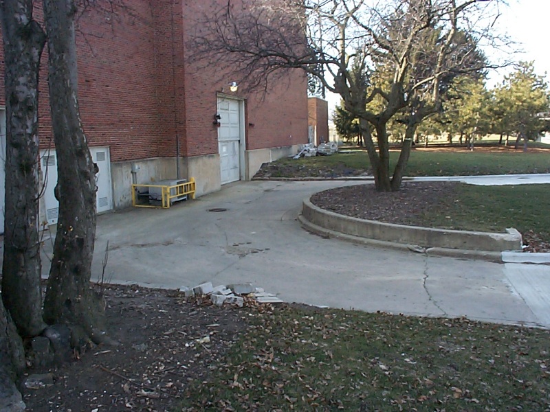
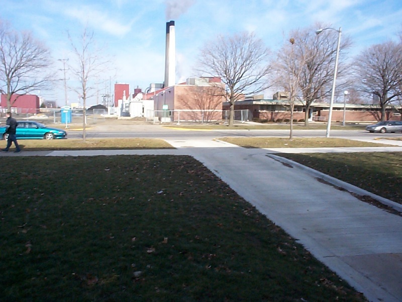
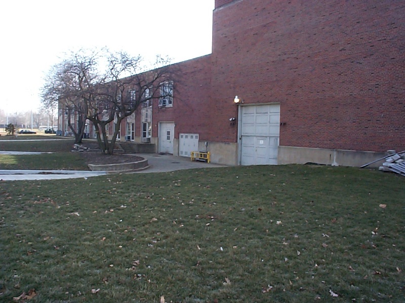
A truck can back up between the tracks and the spectrometer is then lowered onto the trailer and finally covered with a tarp. Other trucks are necessary to transport the heads, power supply and other hardware. The orientation of the truck shown avoids having to drive under the bridge between Stadium Drive and Neil Street to the west. (Shown below at the left of the third picture in the top row below.) Photos of the exterior of the NPL Barn at UIUC
These photos show details of the exterior of the NPL barn and the driveway from various angles. Hopefully, some resemblance can be seen between reality and the renderings above.
Back to the G0 Main Menu
Back to the Bartoszek Engineering Home Page
|