Images of the G-0 Experiment at the Jefferson Laboratory, Newport News, VABartoszek Engineering has taken the project engineering role on the G0 experiment from its conception. We produced most of the mechanical drawings through the RFP process to find a prime contractor to build the cryostat and coils. Bartoszek Engineering is also responsible for the design of the lead shielding used to collimate the particles from the target to the detectors, the vacuum windows, the support carriage for the spectrometer, the cold optical measurement of the device, the shielding on the upstream and downstream heads, and the laser alignment system used during magnetic field measurement. Recently, we have been involved in designing a modification to the support carriage used at Jefferson Lab, and a new shipping fixture for the cryostat. Link to a Powerpoint web presentation of the Back Angle Upstream Shielding Design Right click here to download the native Powerpoint file of the design. (Added on 10/23/05)
These are photos of the G0 shipping fixture in fabrication at Dial on 2/18/01. (posted on 2/18/02.)
These are new rendered images of the necessary steps in the rotation and movement of the G0 cryostat to get it from inside the NPL barn and onto a truck headed to JLab. (Updated on 1/15/02.)
These are new rendered images of the design and assembly of the cryostat shipping fixture. (Posted on 12/21/01.)
These are rendered images of the redesign of the G0 Carriage which incorporates linear bearings at the floor. These bearings allow the spectrometer to be moved in and out of the beamline, while the layers above the bearings preserve the original alignment degrees of freedom. (Posted on 9/3/01.)
A series of rendered images created from the solid models of the reference conceptual design for G0. This page gives an overview of what the whole spectrometer was originally designed to look like.
A look at the process to cast the lead blocks for the collimators. Casting happened at Vulcan Lead Products in Milwaukee, WI. The sand molds were provided by CasTech, Inc, also in Milwaukee.
These pictures were taken at the NPL barn at the University of Illinois in Urbana-Champaign during the assembly of the first collimator module.
Photos of the vacuum window test that was performed at UIUC on 12/13/99. The test was a vacuum and pressure test of a .020" thick titanium window that seals the vacuum of the spectrometer but lets the radiation from the target through to get to the detectors.
UNDER CONSTRUCTION
Photos of the spectrometer in the barn at NPL and the laser alignment system that BE designed for G0. You are welcome to download any of the images. If they are used for other than private viewing, credit to Bartoszek Engineering would be appreciated. Back to the Bartoszek Engineering Home Page |
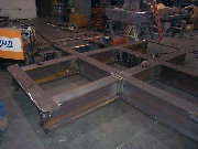 Status of the G0 Shipping Fixture fabrication, 2/18/02
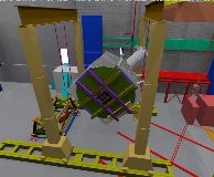 Link to Steps in Moving the G0 Spectrometer Page
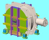 Link to the Design of the Cryostat Shipping Fixture Page
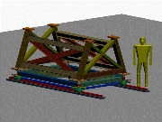 Link to the Design of the Carriage Modification Page
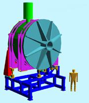 Link to the G0 Renderings Page
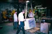 Link to the Lead Casting Page
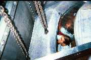 Link to the Collimator Assembly Page
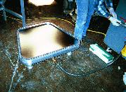 Link to the First Vacuum Window Test page
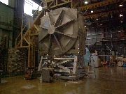 Link to Photos of the Spectrometer in the NPL Barn page