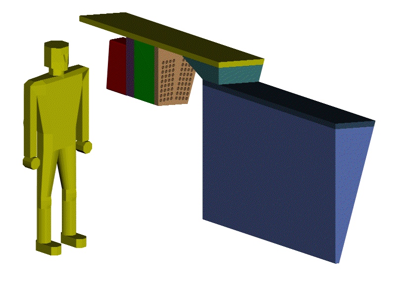
The following pictures show the major structural features of the HF wedge. I did not go into detail on the light tighting sheath or the box around the fibers. The assembly scenario is not changed by these details. They do however complicate the lifting points of the wedge. Throughout the assembly scenario I have assumed that there are four pick points (tapped holes) in the corners of the absorber on both sides that face other wedges. I have not calculated the size of these holes, but the weight of the wedge leads me to believe that they are not excessively large.
The red boxes nearest the man in the picture are the PMT enclosures. These are bolted to the steel shield immediately upstream of them. This piece of steel is suspended from the yellow plate by bolts, as is the other steel shield plate upstream of that. The green wedge between the two is a stack of 50 mm thick plates of borated polyethlyene (holes cut for the light guides). I am imagining that the steel sheets sandwich the poly and that there are threaded rods that support the poly off of the steel plates.
The yellow steel plate is connected to the absorber back plate through the wedge shaped shim by bolts. The darker blue absorber back plate is welded to the Russian absorber blocks and has tapped holes to fasten the shielding plates assembled later.
This wedge design differs from a previously shown version in that the back surface of the wedge is a single flat plate. The diffusion welded plates are all parallel in this design. I believe this is critical to simplifying the support structure and guaranteeing the tolerances needed for assembly.
You are welcome to download any of the images. If they are used for other than private viewing, credit to Bartoszek Engineering would be appreciated.
 View of wedge from off the IP, 115K
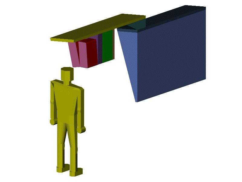
 View of wedge looking toward IP , 81K
Forward to installing wedges on the lower cradle
Back to the HF Conceptual Design Table of Contents
Back to the Bartoszek Engineering Home Page