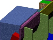
These pictures show how wedges are assembled from the bottom up on the lower cradle. The wedges in the lower half are attached to the cradle by bolts. They have no need of shear resisting features between them because gravity is forcing them to fall into the support cradle. The inside radius connection between wedges is slightly problematic because of the small space and the fact that the fibers are installed before wedge assembly. I believe it is possible to do small skip welds between wedges on the inside radius even with the fibers installed, but this can be tested and verified.
Wedges in the top half of the assembly want to slide down the ramped faces of the ones below them. For this reason, there is a stepped feature in the shielding plate bolted to the wedge back plate that catches the wedge below it and prevents it from slipping down during assembly. An implication of this design is that each wedge needs to be lowered into place at the same angle it occupies in the assembly. Wedges cannot be rotated into place the way the HB wedges are assembled because the step will not engage properly and the cradle is not compatible with the wedge bracket design the HB uses. Top half wedges would be welded together at the step interface to make their connection secure to the lower wedges, as well as skip welding the inside surface as before.
You are welcome to download any of the images. If they are used for other than private viewing, credit to Bartoszek Engineering would be appreciated.
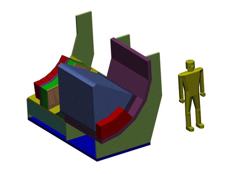
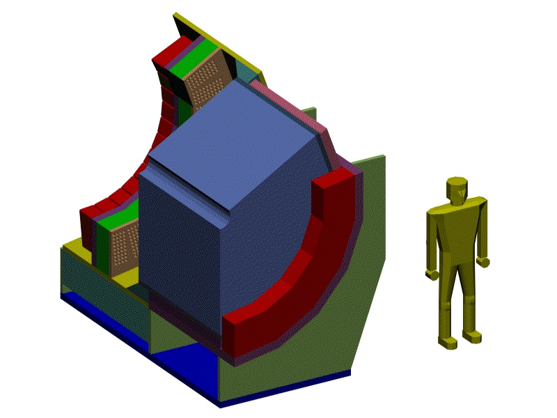
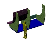
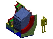
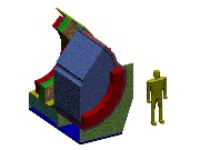
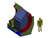
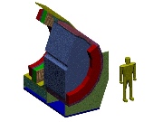
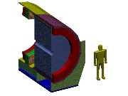
 Iso view of welded cradle structure, 107K
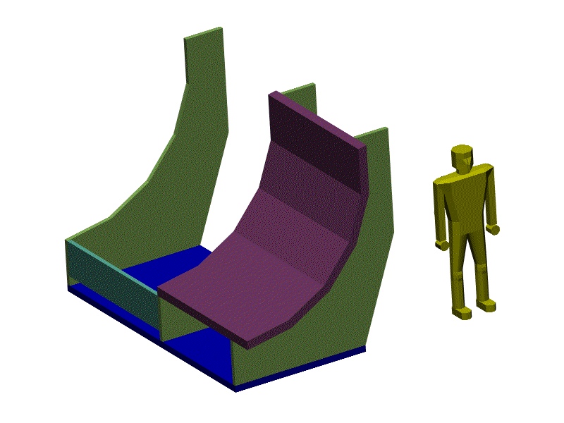
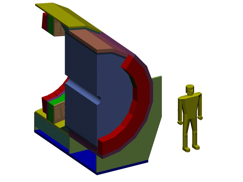
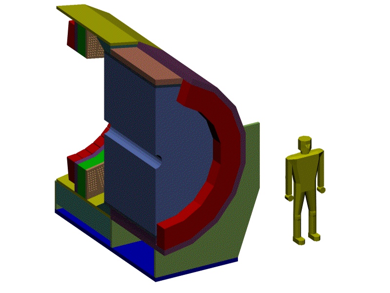
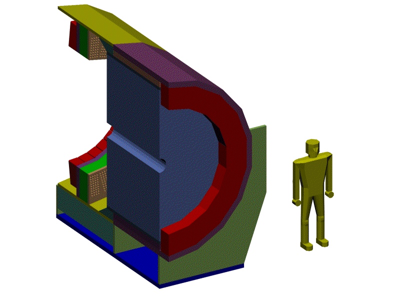
This structure is fabricated as a unit. The purple steel plates welded to the vertical plates serve two purposes. They have through holes to allow the wedges to be bolted into place, and they act as part of the outer layer of steel shielding. It is understood that there are more features to add to this structure to allow the motion and alignment necessary in the detector hall at CERN. Note that the wedges are not in contact with the downstream cradle plate at all. (They look close, but a gap is essential to avoid loading the PMT box area.)
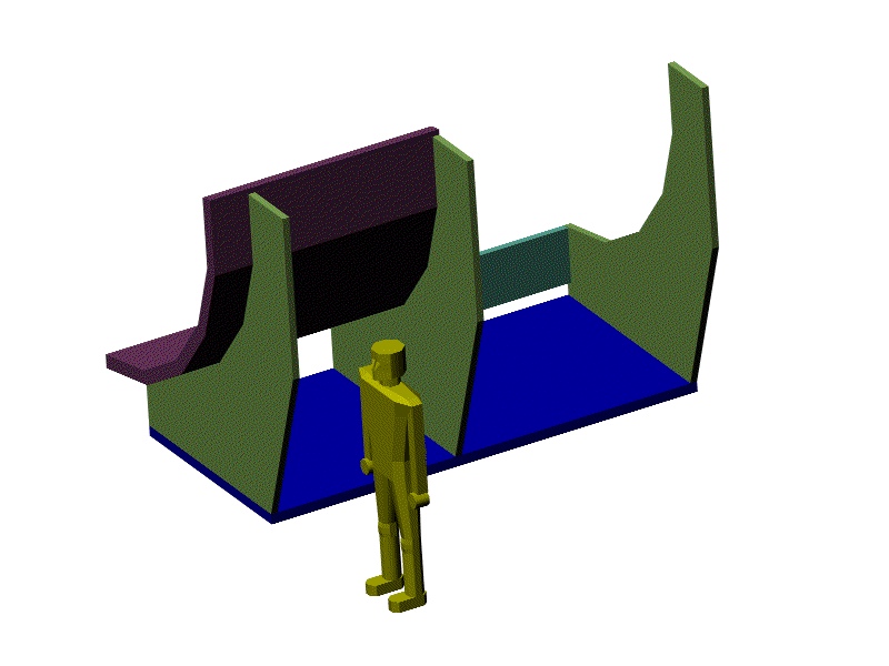
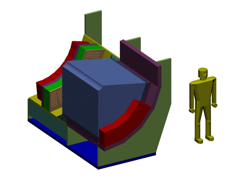
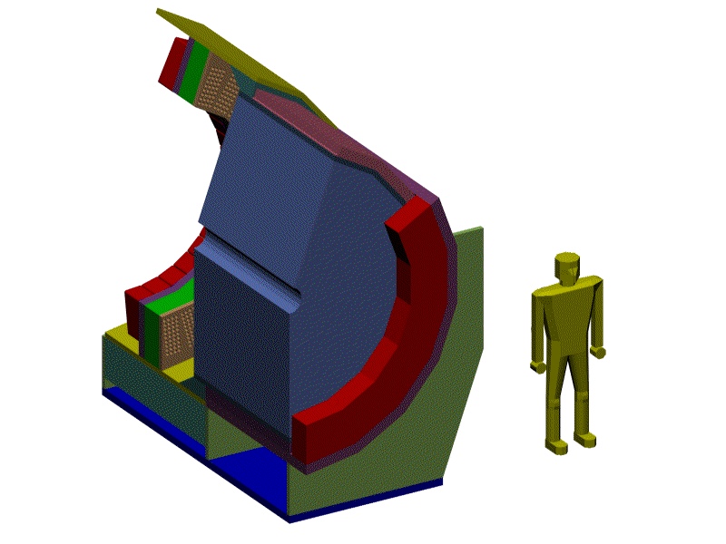
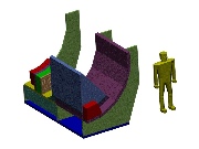
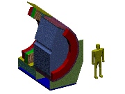
 Another iso view of the cradle, 82K
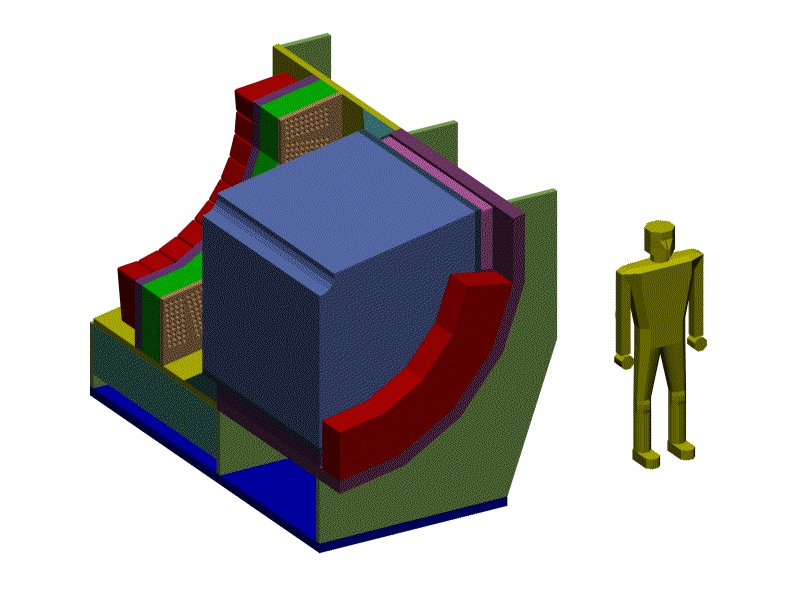
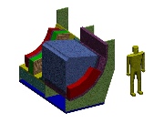
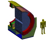
 The first wedge is mounted, 113K
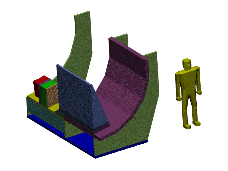
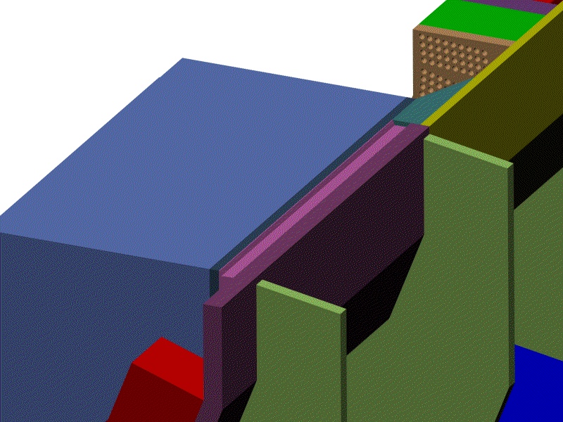
Before the wedge is lowered onto the cradle, another piece of steel shielding plate is bolted to the welded back plate of the wedge. In this picture, that plate is a darker purple than those of the cradle. The cradle plates have through holes that allow the wedges to be bolted to the cradle from below. The next picture makes clear why the cradle plates overhang the wedge shielding plates.
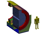
 Second wedge mounting after upstream shielding, 114K
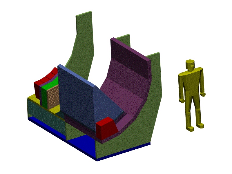
The red block upstream of the absorber is another steel shielding block attached to the purple cradle plates.
 Third wedge mounted, 116K
This process repeats up to the mid plane wedge.
 Fourth wedge mounted, 118K
 Fifth wedge mounted, 120K
This is the mid plane wedge, and the color of its bolted on shielding plate is different from previous ones because it has the female notch that accepts the male protrusion from the next wedge up to keep the next wedge from sliding down toward the beam line.
 Close-up of notch on mid-plane wedge, 231K
This image shows the contour of the notch. The next wedge up has yet another design of shielding plate that has a matching male protrusion, and a female notch on the opposite side to catch the next wedge up. The original design intent was to weld the upper wedges to the lower along the notched plates with a skip weld, but this could conceivably be redesigned to be a bolted connection if necessary. The size of the notch would almost certainly get bigger to do this.
 Sixth wedge assembled, 123K
This is the first wedge that hangs from the lower wedges.
 Seventh wedge assembled, 108K
 Installing the outer shielding plate on the sixth wedge, 108K
At this point it makes sense to attach the outer shielding plate to the sixth wedge as a unit with its matching upstream block of shielding. These plates and blocks are treated differently for the upper half of the assembly because there is no cradle for them to be attached to.
 Eighth wedge assembled, 109K
 Installing the outer shielding on the seventh wedge, 110K
 Ninth (and last) wedge assembled, 113K
 Installing the outer shield on the eighth wedge, 113K
 Installing the outer shield on the ninth wedge, 112K
Notice that there is a fourth design of outer shield plate here because there is no need for the female notch on the center plane of the detector.
Forward to installing concrete and poly on the lower half
Back to the HF Conceptual Design Table of Contents
Back to the Bartoszek Engineering Home Page