First Redesign of the Collimator Shielding, 1/03These pictures show the conceptual design of the new collimator shielding. This design attempted to use existing steel plate shapes but has several modified plates that would require cutting some of the already purchased steel plates. The next iteration will attempt to minimize the modifications of plates. (Modifications were driven by holding to an overall envelope that there is some freedom on changing.) The wheels shown are provisional as it is not currently known if they will work without spalling the concrete of the Booster floor. The steps required to make the transition to shielded collimators is to first remove the collimators from the beam line and modify them to be attached to a new rolling dolly cart. The cart comes partially assembled with steel plates which still allow the collimator and stand to be attached. Additional shielding is then added above ground until the weight of the module approaches the capacity of the Booster access hatch crane. After the modules are lowered into the Booster, additional steel plates are added and secured. The final module is then rolled down the tunnel and installed in the vacuum pipe of the Booster. If the collimators are too radioactive to bring above ground, the partial shielding cart could be lowered and the remaining assembly could all be done in the Booster access tunnel. Click on any of the thumbnails to get an enlarged view. You are welcome to download any of the images. If they are used for other than private viewing, credit to Bartoszek Engineering would be appreciated.
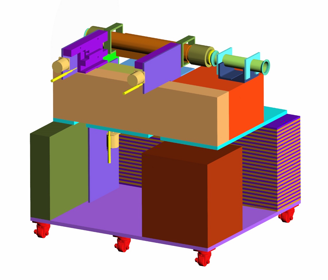
Two views of an incomplete module that weighs less than seven tons
The motivation for creating this configuration is to show what the shielding cart would look like if its weight were limited to less than the capacity of the crane over the Booster access hatch. Most of the assembly work would be accomplished above ground, and this module would then be lowered into the Booster. The remaining shielding would be stacked around it in the Booster access tunnel, and then the completed units would be rolled into place in the Booster long straight sections.
Note the short length of beam pipe supported on the downstream shielding. This spool allows access to vacuum flanges outside the shielding block. It can be made alignable.
Two views of the completed module
These views show what a completed collimator/shielding module would look like. The minimum thickness of shielding around the collimator is 12 inches of steel. This steel would never be removed from around the collimator. The image on the right is what it will look like seen from the aisle. The left image is the side that faces the wall of the Booster inside the beam pipe.
The design is intended to be modular in the sense that this would be rolled completely out of the Booster beam if it were unrepairable in place. Another would be rolled in and attached to the Booster vacuum pipe in that case. Another aspect of its modularity is that additional shielding could be added if activation levels at the surface of the shielding became too high. At that point the motors and collimators would not be repairable because they would be covered in shielding, but the cart could still be rolled out and replaced in toto. Back to the Booster Collimator Shielding Main Menu Back to the Bartoszek Engineering Home Page |