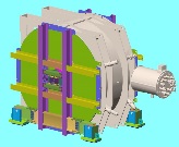
Design of the G0 Cryostat Shipping Fixture, 12/21/01The pictures that follow present the design of the G0 Cryostat shipping fixture, and the steps required to assemble it. The purpose of this page is to inform UIUC and JLab personnel of the status of the design and to invite comments prior to the detailed drawing stage and fabrication. Click on any of the thumbnails to get an enlarged view. You are welcome to download any of the images. If they are used for other than private viewing, credit to Bartoszek Engineering would be appreciated.
Installation of the Center Beam The center beam is the main structural support of the cold mass inside the cryostat during shipping. It engages the hubs on both ends of the magnets and carries the cold mass load out to the welded frame shown below. One of the big challenges of this design is to make the connections and members robust enough to support the load from several different directions. All members and connections were designed to limit the deflection in any direction to 1/8", and absorb a 50% overload above the static weight from transportation and crane handling.
The red hubs are installed on the magnet first and temporarily held in place by clamps, and then the center beam is poked through from one end. The crane handling of this operation is accomplished with an extension beam bolted to the end of the 10" x 10" x 1/2" box beam that allows the crane to balance the beam with enough length to completely penetrate the cryostat.
The "Water-tight" Covers These plates effect the sealing of the cryostat during shipping and installation at Hall C except for the small region around the center beam protrusion, which will be handled with some kind of plastic and adhesive sealant. The o-ring will be left in the groove on the cryostat. The plates are 1/4" thick sheepts of aluminum, and there are two different sets of features welded to both sides of the plates. The tan rectangular bars on the outside allow the plates to be bolted to the welded shipping frame, which gives the plates enough strength to be walked on when the cryostat is horizontal.
The circular bosses and rods on the inside act as adjustable length bumpers that transmit load from the cold mass to the shipping frame at a larger radius than is done by the center beam. The bosses on the downstream end are particularly important as they protect the octagon ring-to-coil bolted connection from potentially being overloaded by collimator forces when the magnet is handled beam axis vertical. There are circular bumper plates on the outside of the water tight covers that take the loads from the bosses through the green plates and out to the welded frame without creating water leak holes. The length of the bumpers will be adjusted as the covers are attached to assure engagement with features on the magnet. Contact with the upstream longer bumper rods is optional as they are only there for unusual rocking forces during shipping.
Cover Installed with the Center Beam Protruding This picture shows the area that needs additional water-proofing after the covers are assembled. The gaps are necessary to allow for inaccuracies between all the different parts being connected together.
Attachment of the Shipping Fixture Welded Frames In this stage, the welded frames are bolted onto the remaining holes on the cryostat flanges. The water tight covers can then be bolted to the frames. At this point we are ready to connect the center beam to the welded frames.
Beginning the Connection between the Center Beam and the Welded Frames This picture shows the first plates to be attached to the center beams to transfer loads out to the welded frame. All bolts in this connection area are 1.000"-8 of several lengths that shall be tightened by either torque wrench or turn-of-the-nut method to their full recommended values. The connections between the center beam and the welded frame are combinations of bearing and slip-critical connections, so adequate bolt pre-load is absolutely essential to proper load carrying ability. Clearances for tools have been checked in the solid model and changes were made to increase the clearance for the large wrenches needed.
Center Connection Complete This picture shows the combination of tube sections and angles necessary to complete the connection. Again, the challenge here was to make sure that the connection could take loads in several orthogonal planes as the cryostat is rolled around all of its axes, and that human beings could assemble it.
Cryostat Rolled Horizontal In this position the cryostat would be supported on wooden cribbing in preparation for attaching the feet that allow the cryostat to roll out of the barn at NPL and down the tunnel into Hall C at JLab. The stubs of beam at the bottom had to be cut off from the full length because these beams covered pick points on the cryostat shell. Crane cables could not be connected nor run over these beams because the load during cryostat rotation would have been on the beam in its weak orientation and it would not have survived. A bolted moment connection allows the feet to be attached as shown in the next picture.
Removable Feet Attached Here, the feet are attached. The cryostat is ready to begin its journey to Jlab.
Close-up of Foot Connection The feet are designed to allow several different models of roller to be used if the intended ones become unavailable. Set screws are used to take up gaps between the feet and the rollers, as well as slightly modifying the angle of the rollers with respect to the cryostat. Back to the G0 Main Menu Back to the Bartoszek Engineering Home Page |


