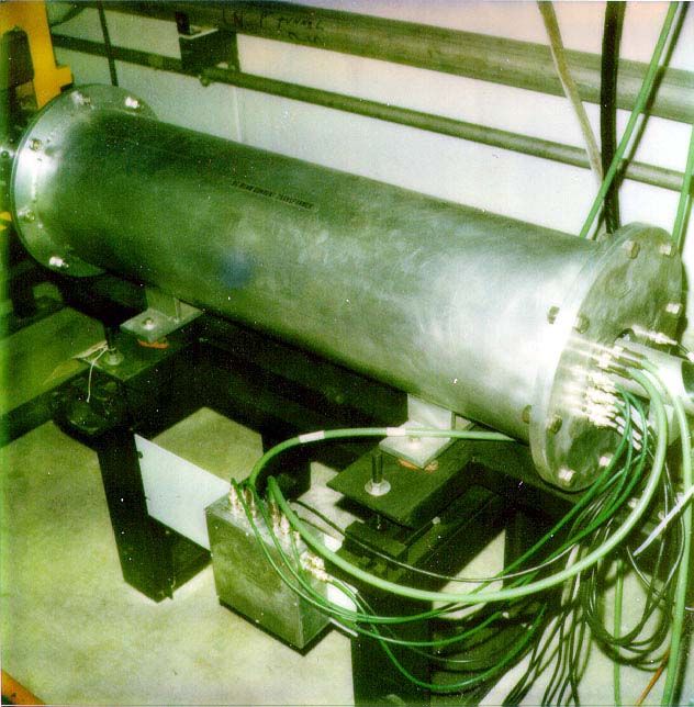
Photos of some Beam Diagnostics Larry Bartoszek worked on at FermilabBeam diagnostics are devices which allow operators in the accelerator control room to know what is happening to the beam inside the beam pipe down in the tunnel. Larry Bartoszek worked on many different kinds of beam diagnostics over his years at Fermilab. The first two pictures show the DC Current Transducer used to measure the amount of antiprotons stored in the Accumulator beam. Electrical design was done by Jeff Petter. The next three pictures showcase the wide-band pick-ups in the Accumulator. The next two pictures show two versions of the beam loss monitors. The following two pictures show a typical beam damper. Beam dampers are similar in concept to the stochastic cooling system in the Antiproton Source. They sense fluctuations in the beam at a much lower frequency than the gigahertz stochastic cooling system, but they too send a signal to another point across the ring to correct the beam. Larry Bartoszek took these pictures while employed at Fermilab. (Presentation of photos from Fermilab does not imply endorsement of any product or service.) You are welcome to download any of the images. If they are used for other than private viewing, credit to Bartoszek Engineering and Fermilab would be appreciated.
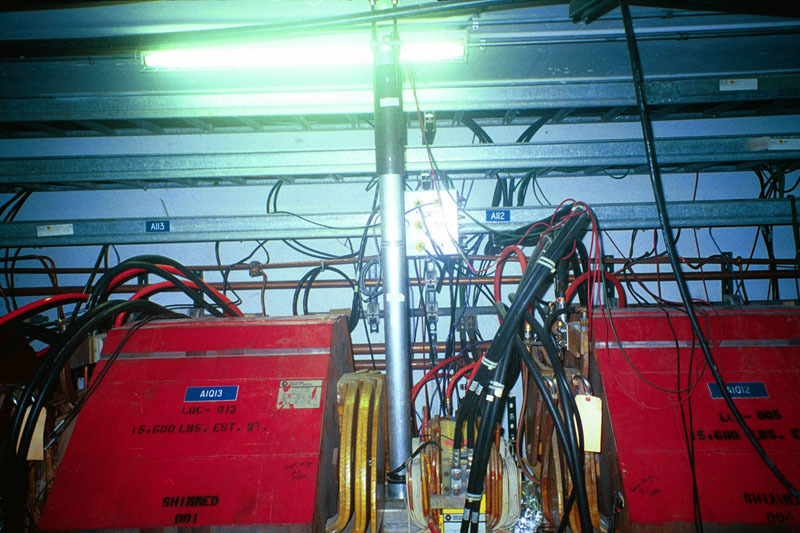
This device collects high frequency signals from the antiprotons flying through the beam pipe in the center of the device. The signal collection is done by a group of ferrite doughnuts surrounding the beam pipe wrapped with many windings of fine wire. Analysis of the signal allows the antiprotons to be "counted" giving a measure of the stored beam current. The beam pipe is not continuous through this device, but is broken in the center by a ceramic doughnut sealed to the pipe on both sides with a vacuum tight braze joint.
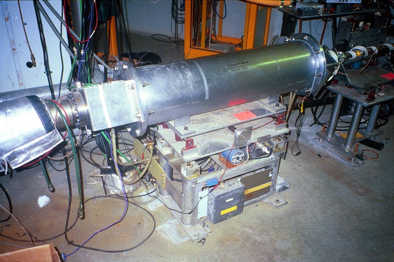
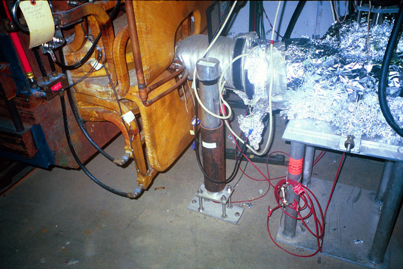
This is a later version of the DCCT also outfitted with a new motorized stand because of its small aperture.
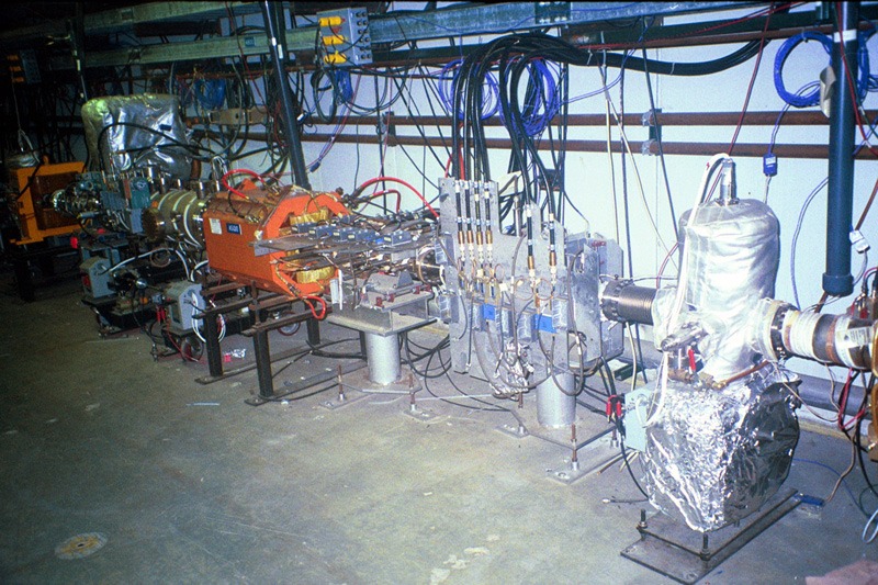
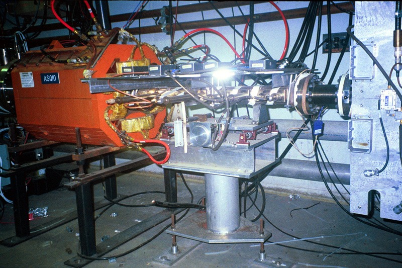
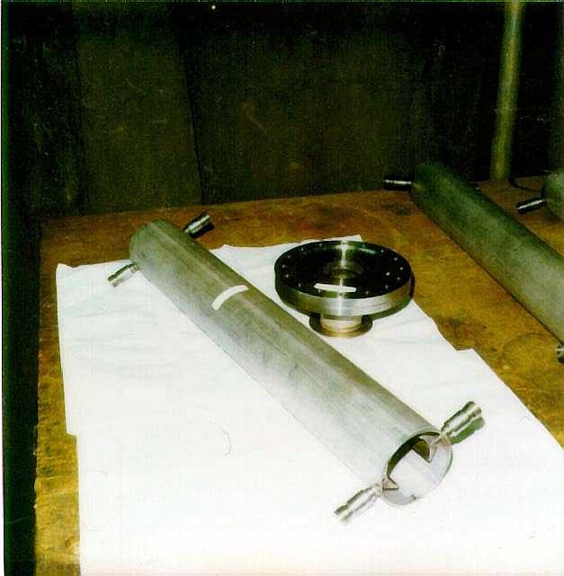
Wide band pick-ups are devices that sense a wider band of frequencies of the beam as it oscillates than some other beam diagnostic systems. They are oriented both vertically and horizontally to pick up oscillations in both axes.
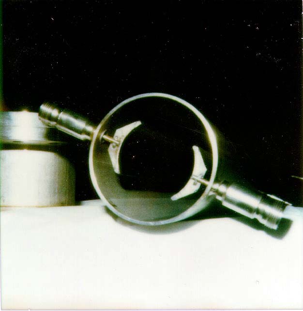
This view emphasizes the amplifier electronics mounted to the vacuum chamber.
This view shows off the weldment of the stainless steel vacuum chamber. Inside the "bump-outs" on the vacuum tube are plate electrodes connected to the long tubes that feedthrough for the electrical connectors. All of the beam diagnostics in the Accumulator have to be designed considering the frequency that they sense, as well as being impedance matched to the beam pipe so that there will be no undesired RF cavities produced by changes in the geometry of the beam pipe.
Beam loss monitors are very simple devices. They are scintillating plastic cookies which give off light when radiation passes through them. The cookies are located directly inside the caps of the device right next to the beam pipe (to be closest to where the losses happen.) The light is registered in a photomultiplier tube (PMT) and converted to an electrical signal that is routed to the control room. The PMT is very sensitive to magnetic fields, so it is placed inside a soft iron pipe as far away from the magnet ends as possible. To get the light from the scintillating cookie to the PMT there is an acrylic rod of light pipe which has the cookie glued to one end. The light pipe runs through the outer aluminum pipe to the PMT on its other end.
Some loss monitors cannot be mounted to the ceiling, so they are designed to be floor mounted. Loss monitors work in concert with scrapers to sense where the beam is. When a scraper is moved into the beam the particles that hit it spiral out of the ring and hit the loss monitors, lighting them up. The position of the scraper jaw is monitored so that the edges of the beam are known by correlating the signal in the loss monitors with the position of the scraper jaws.
Beam dampers have coaxial pickup electrodes running down their length on both sides of the pipe. When the beam passes through this assembly a signal is induced on the electrodes which is carried out of the damper by coaxial ceramic electrical feed-throughs (the protuberances on both ends of the device.) The damper system is made up of pick-ups that sense the signal on one side of the ring and kickers which modify the beam on the opposite side of the ring. Lower frequency oscillations (compared to the stochastic cooling system) can be dampened out by this system. Larry Bartoszek worked on many such devices, including the wide-band pickup (not shown) and was responsible for the mechanical design and installation of most of the beam diagnostic devices in the Antiproton Source tunnel.
This view shows some of the details associated with the very fine welds between the ceramic feed-throughs and the electrodes. These coaxial feed-throughs cost several hundred dollars each so welding was performed extremely carefully to avoid cracking the ceramic.
Back to the Projects Main Menu
Back to the People Main Menu
Back to the Bartoszek Engineering Home Page
|