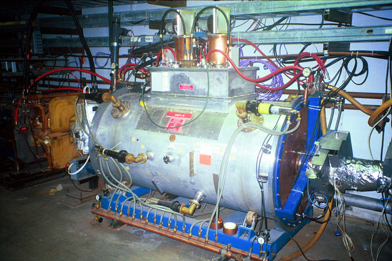
Photos of the ARF-1 RF Cavity Larry Bartoszek worked on at FermilabRadio Frequency (RF) cavities are how particle accelerators accelerate the charged particles that circulate inside them. Radio frequency energy is pumped into the cavity at precise frequencies and at certain times in the machine cycle. In a typical RF cavity application particles are either accelerated or decelerated into bunches. RF is used in many ways in a particle accelerator to inject and extract beam from one machine to another, and increase the beam's energy for fixed target and collider experiments. Larry worked on many different aspects of this cavity. The cavity needed a method of changing its tune remotely. There were several experiments in tuning the cavity before settling on the mechanism shown in the second picture. The basic idea of tuning is to put a volume of material in the cavity and move it around to adjust the resonant frequency of the cavity. The final mechanism shown uses a chain drive to rotate G-7 threaded rods that poke into the cavity. The G-7 rods act like a screw jack with nuts embedded in the copper clam shell assembled around the beam pipe. (Unfortunately, all of this is hidden inside the cavity.) Larry also worked on designing the plumbing to water cool the cavity's RF power tubes at the top. This was initially a big problem because the first tubes on the cavity were not rated for the pressure of the Low Conductivity Water (LCW) system in the tunnel. The solution was to use a regulator to lower the water pressure from the LCW supply header into the tubes and then use a PD pump to pump the water into the LCW return header. This system was eventually discarded when new power tubes with higher pressure ratings were found. Larry Bartoszek took these pictures while employed at Fermilab. (Presentation of photos from Fermilab does not imply endorsement of any product or service.) You are welcome to download any of the images. If they are used for other than private viewing, credit to Bartoszek Engineering and Fermilab would be appreciated.
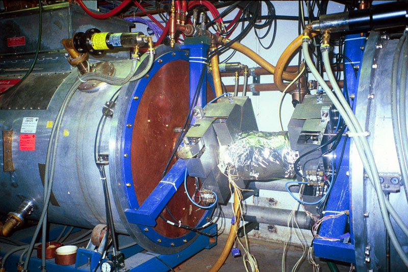
This is a photo of the ARF-1 cavity in the AntiProton Source Accumulator. The top of the cavity contains the RF power tubes which couple energy into the cavity beneath. The tuners can be seen on the ends of the cavity near the beam pipe in the middle.
Most of what is visible in the photo above is the sheet metal chain guard that surrounds the drive mechanism. Inside the guard, a roller chain drive mechanism rotates threaded rods that push or pull copper shells that are assembled around the beam pipe. The shells are keyed to slide along the beam pipe to adjust the cavity's natural resonant frequency. This was the first entirely CAD-based design job Larry did on a Macintosh using MacDraft II, back in about 1985.
Back to the Projects Main Menu
Back to the People Main Menu
Back to the Bartoszek Engineering Home Page
|