Images of the construction of the OOPS Gantry, up to the mounting of the Lower OOPSThese photos show the construction of the OOPS Gantry Air Caster Base, Columns, and the Mid Mount Assemblies at the Bates Laboratory. They are provided courtesy of Stan Sobczynski of Bates, and MIT. When complete, it will be able to position two 16 ton OOPS modules and point them at the scattering chamber target in the South Hall.
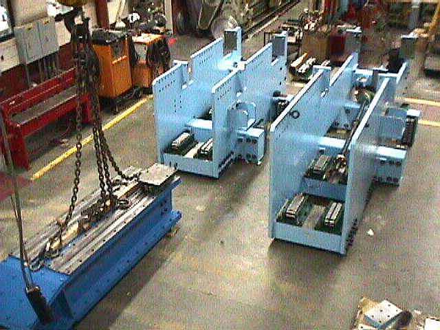
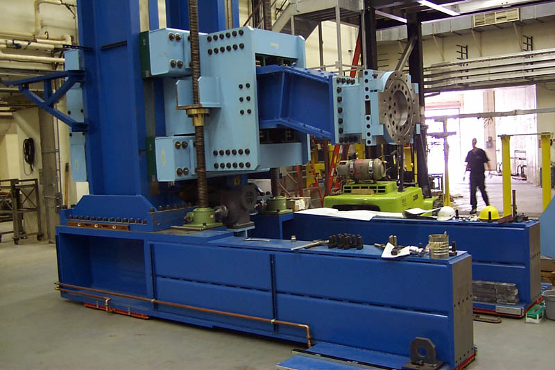
The Mid Mount Assemblies were assembled in the High Bay at Bates. These are the transition pieces which are supported by the vertical screw jacks, and contain the horizontal jacking mechanism. They contain all of the Hilman rollers which allow vertical and horizontal positioning of the OOPS module. In the left foreground is the lower cantilever beam.
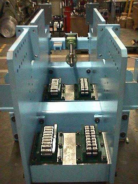
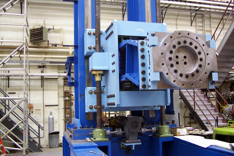
This photo shows more detail in the Lower Mid Mount Assembly. You can see the 100 ton Hilman Rollers for the Lower Radial drive mechanism. The ones on the right are keyed to guide the motion to within .010". The screw jack in the back is the horizontal (radial) drive. It couples to the lower cantilever beam and pushes it in and out.
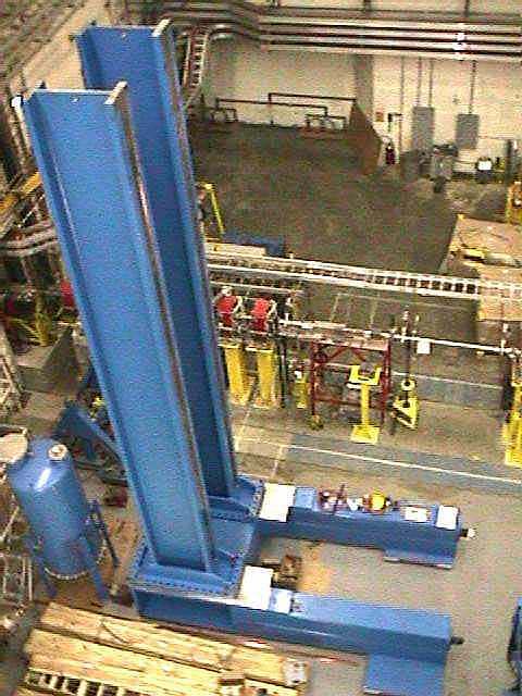
The columns that carry the bending moment from two OOPS modules and their supports are W36x650 beams. These beams are not manufactured domestically and were purchased from a steel supplier in Belgium. They were welded and machined at APEC, a shipyard in Hingham, MA, along with the air caster frame.
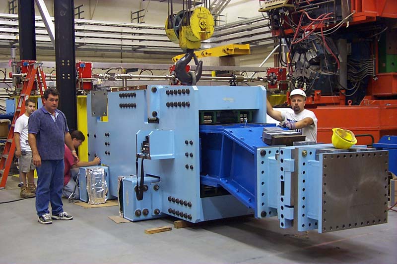
This photo shows the Lower Mid Mount Assembly with the Lower Cantilever ready to be lowered over the columns. This assembly weighs just over 20 tons. There is a tolerance stack-up in this assembly among the parts that create the contact between the vertical Hilman Rollers and the columns. This tolerance stack-up created the need to be able to adjust the distance between vertical Hilman Rollers mounted on the Mid Mount Assemblies. This adjustment was achieved by an adjustable thickness shim between the downstream vertical Hilman rollers and the Mid Mount Assembly. This shim is better seen in some of the images on the OOPS gantry solid models page.
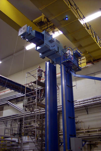
This dramatic shot shows the Lower MId Mount Assembly being lowered onto the columns and air caster base in the South Hall. The vertical Hilman Rollers are also keyed on one column to create vertical tracking repeatable to .010". That is how well the Mid Mount Assembly needs to be matched up to the columns to allow smooth assembly.
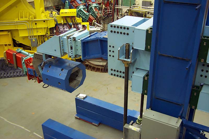
This "close-up" shows the lower vertical jack screws installed on the air caster base and supporting the Lower Radial Assembly. Some of the mechanisms on the end of the lower cantilever are visible here. Each OOPS module has all six degrees of freedom. The design philosophy of the Gantry was to make the three translational degrees "in front of" the three angular degrees, keeping all of the angular adjustments at the end of the cantilever beams for simplicity.
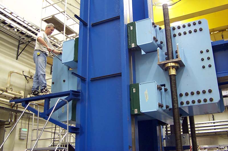
A Bates technician is adjusting the variable thickness shim on the Lower Mid Mount assembly here to guarantee solid contact between the vertical Hilman rollers and the machined troughs in the flanges of the columns. Orthogonality of the vertical and horizontal positioning mechanisms is created by the relationship between the upstream vertical Hilman rollers and the lower horizontal Hilman rollers on the Mid Mount Assembly. The downstream vertical Hilman rollers lock the Mid Mount Assembly to the columns by the preload exerted from the variable shims.
In this view the transition piece between the Roll mechanism and the Lower Yaw mechanism has been removed exposing the Roll bearing. Bartoszek Engineering custom designed these sliding contact bearings to allow small roll adjustments of the OOPS module. These bearings have no rolling elements, but instead use relatively large contact area sliding pads made from Garlock DU material. The large area reduces the contact pressure so far that these bearings are simply made from A36 steel with no heat treating or surface hardening at all. The design was executed to make the roll bearing fit in a smaller space than available standard flange bearings would fit into and at lower cost than standard rolling element bearings.
This view shows the Lower OOPS module attached to the Gantry. The triangular support at the end of the cantilevered beam is the Lower Yaw mechanism. An OOPS module can rotate in yaw at least 25 degrees away from in-line with the Gantry in either direction. One main reason for this feature was to allow repair to take place on the detector package inside the OOPS while it is attached to the gantry. (See next picture.)
This shot from behind the OOPS shows the Lower OOPS with its end cap of lead shielding removed. The cavity in the back of the OOPS is where the detector package goes. (The detectors are not installed in this OOPS yet.) Bartoszek Engineering designed the current end caps, and the detector insertion/extraction mechanism also.
Back to the OOPS Main Menu
Back to the Bartoszek Engineering Home Page
|