|
The SNS Neutron Electric Dipole Moment Experiment (nEDM)
Bartoszek Engineering is working with the University of Illinois on the nEDM experiment. This experiment will be installed at the Spallation Neutron Source (SNS) in Oak Ridge, Tennessee. The experiment hopes to be the most sensitive measurement of the electric dipole moment of the neutron in the world.
Bartoszek Engineering's role initially is to design large aperture superfluid helium tight valves. The experiment operates at between 300 and 500 milliKelvin, so the valves must be mounted and actuated in a way that does not introduce too large of a heat leak to the measurement cells. The valves will have a 3 cm aperture. We did not find anything like valves matching our design requirements either commercially or in other experiments. Part of the uniqueness of these valves is that the materials they can be made from are very restricted to those which are compatible with polarized helium 3, or ultra cold neutrons, and are completely non-magnetic or non-conductive (depending on where they are in the final apparatus.)
The first step in the valve development process was to design a valve seat tester that could test different valve seat configurations under different measured loads. The cryostat started with a borrowed small diameter bucket dewar and a spare G0 valve actuator. The first material tested was kapton sheet squeezed between stainless surfaces. Eventually the stainless will be replaced with either torlon or acrylic.
The design shown was the first pass. Much credit goes to Eric Thorsland and John Blackburn at UIUC for improvements to the original concept. As the design matures, I will include more photos.
Click on any of the thumbnails to get an enlarged view. You are welcome to download any of the images. If they are used for other than private viewing, credit to Bartoszek Engineering would be appreciated.
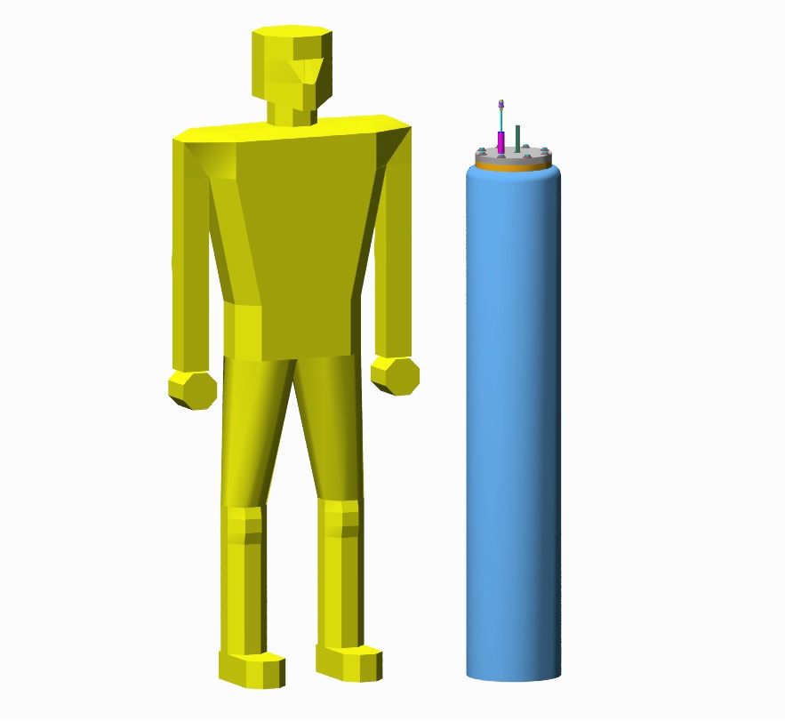
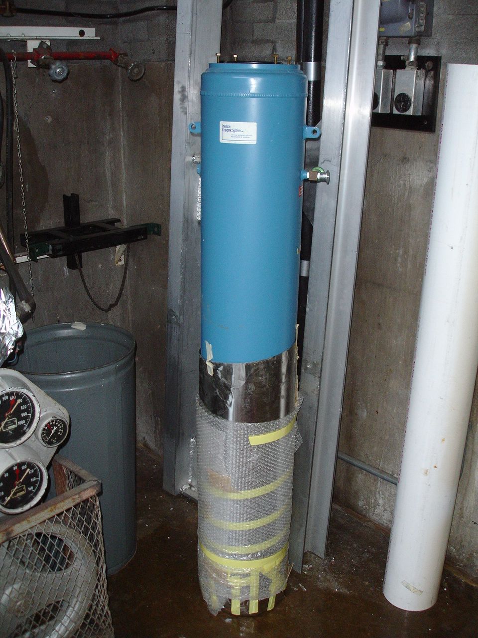
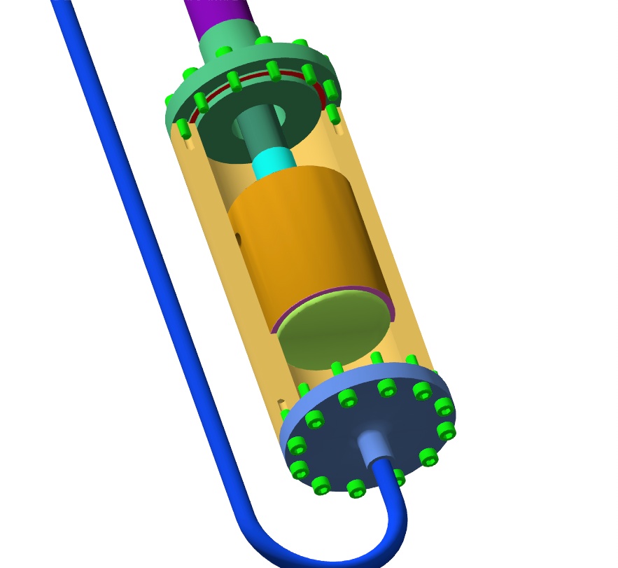
These pictures show overall views of the bucket dewar. When these pictures were rendered, the flange at the top of the vessel was not fully designed.
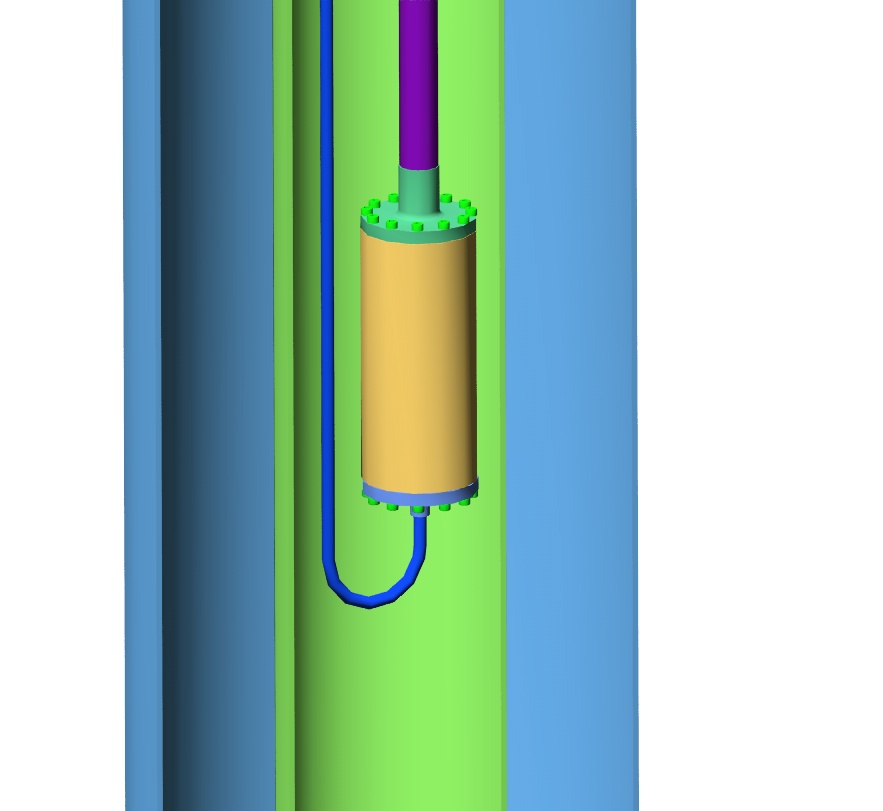
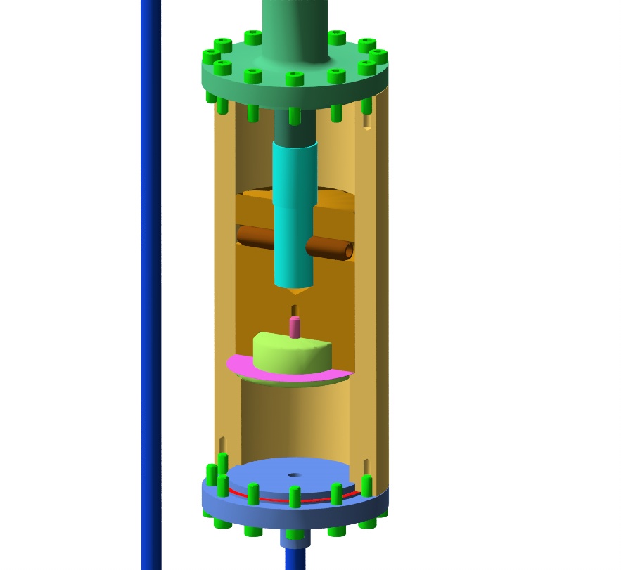
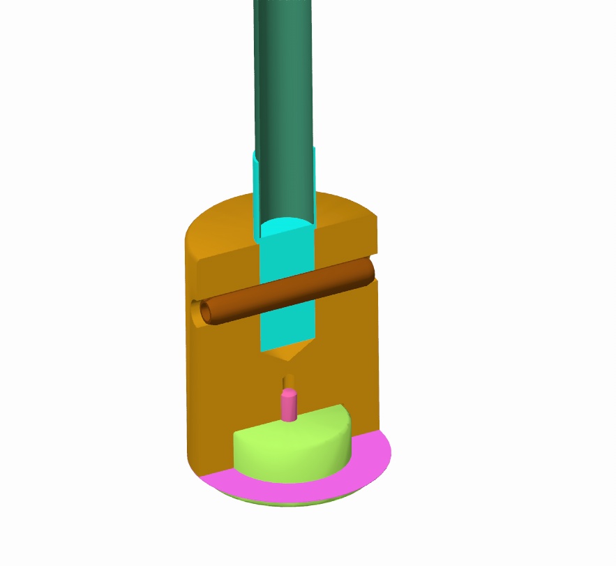
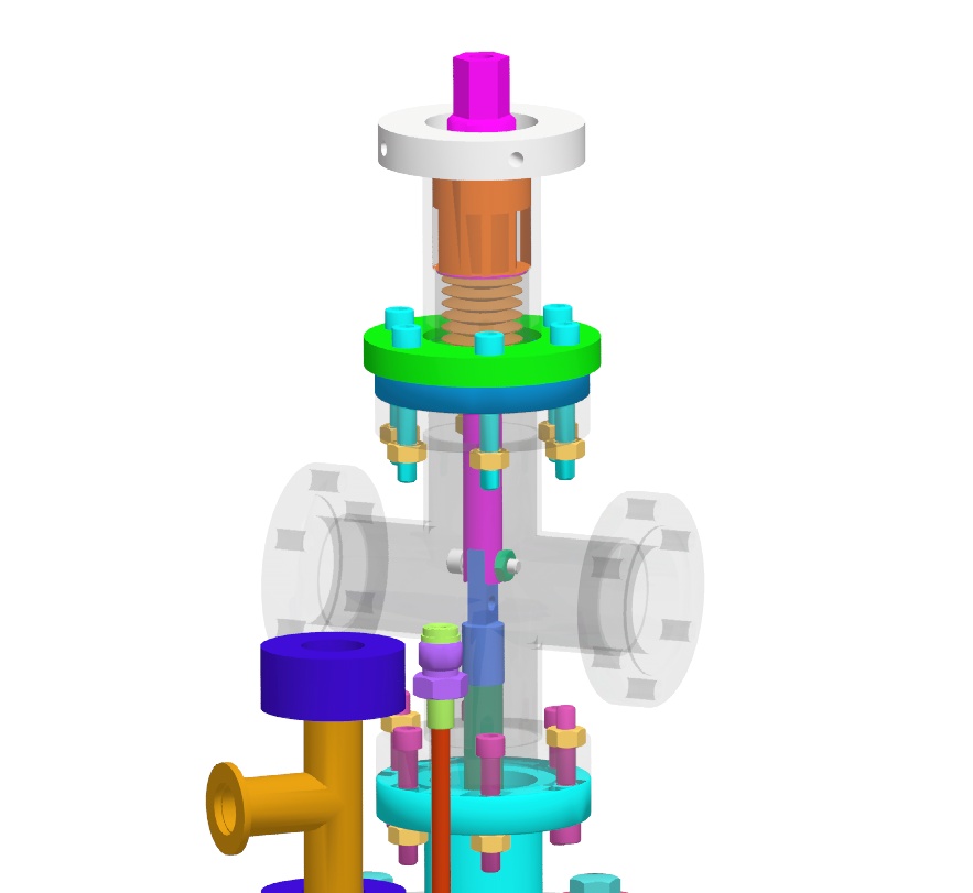
These pictures show the seat tester that is submerged in the bath of liquid helium in the dewar. The leak tightness of the seat is measured by injecting helium gas into the small tube that enters the bottom of the tester. The pressure is measured at the top of the tester, and a helium mass spectrometer monitors for the presence of helium. Measuring the pressure at the top of the tester turned out to be trickier than first thought. New plumbing has been designed (that is not shown in these pictures) to provide a low conductance path up to the pressure transducer which is above the top flange.
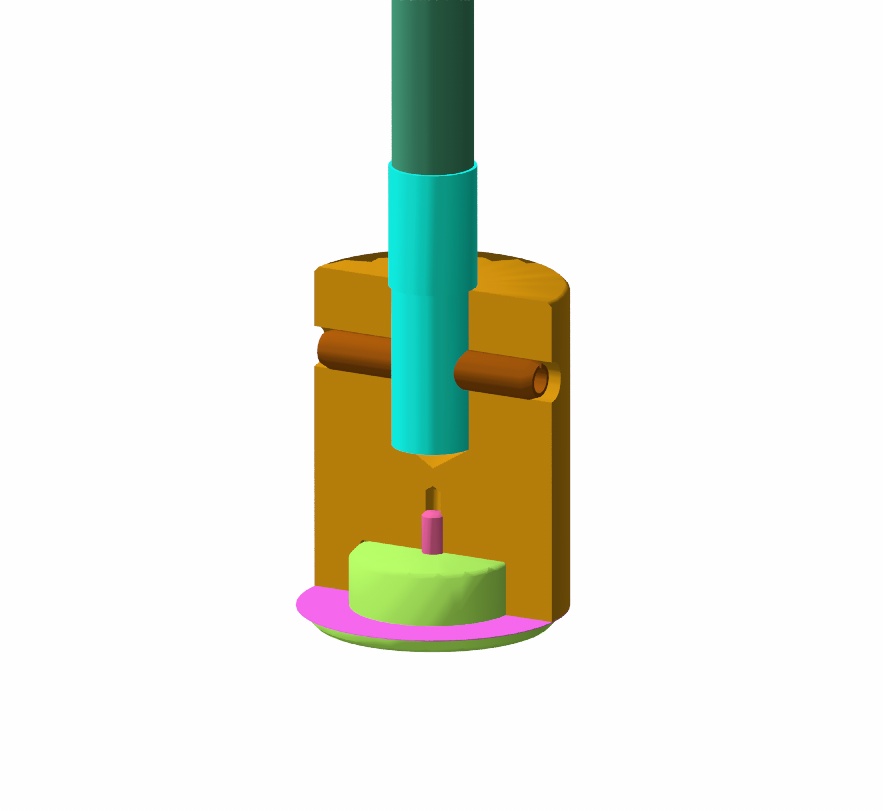
The piston is shown in these pictures. The piston is forced against the valve seat, crushing the kapton sheet to make the seal. Note that the seal tester does not have the large ports that the final valve will have. Any seal leakage goes around the piston to escape the tester and go up the tube that the actuating rod passes through.
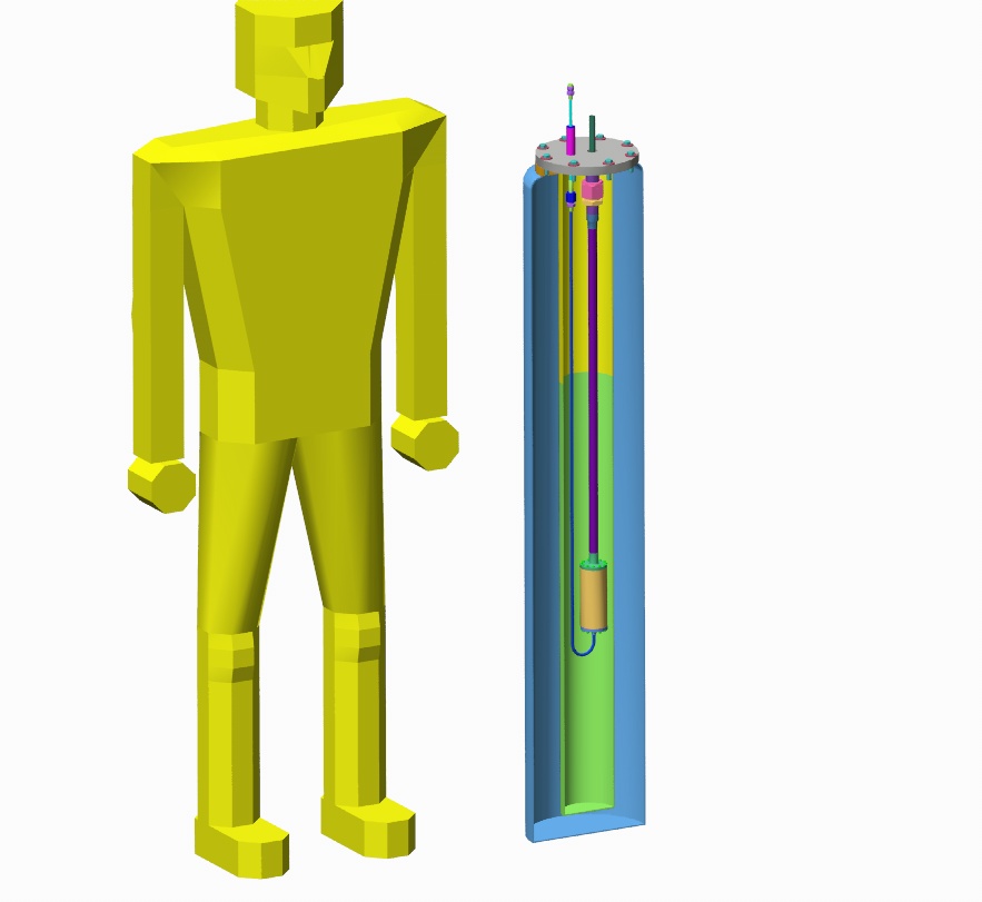
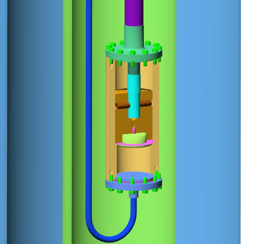
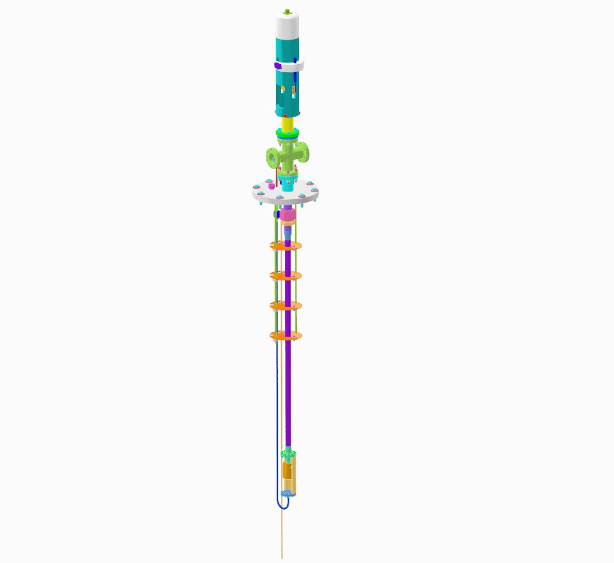
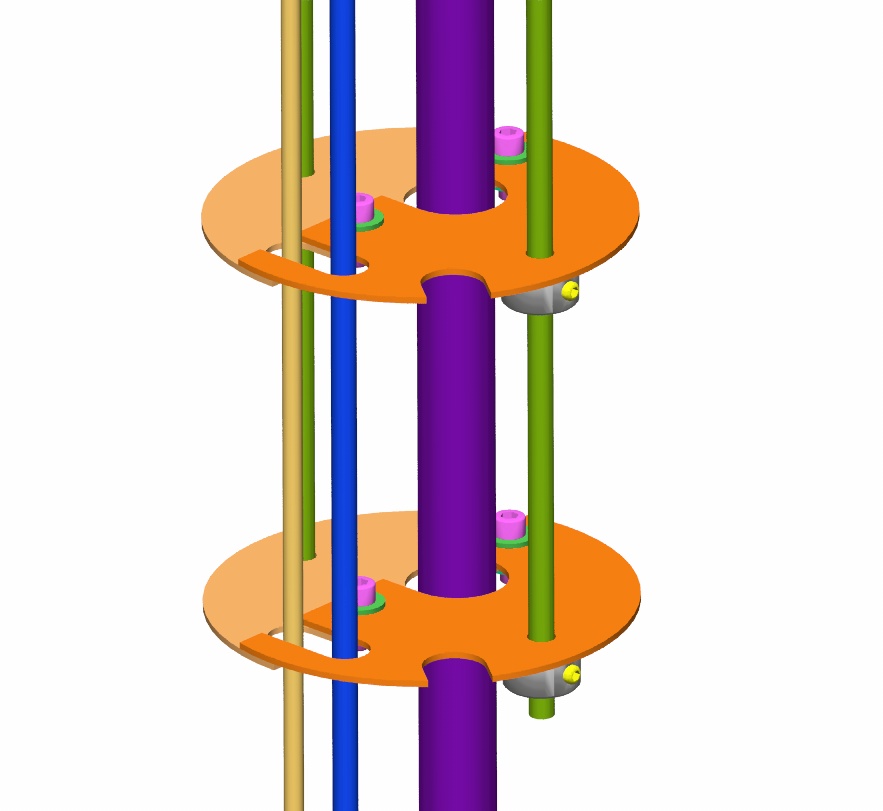
The picture on the left shows the complete insert as it would appear hanging from a crane prior to insertion into the bucket dewar. The picture on the right shows details of the copper plates that act as radiation shields between the bath and the top flange. By vacuum pumping on the helium bath, the temperature of the liquid helium can be lowered below the lambda point of helium 4 and the liquid becomes superfluid.
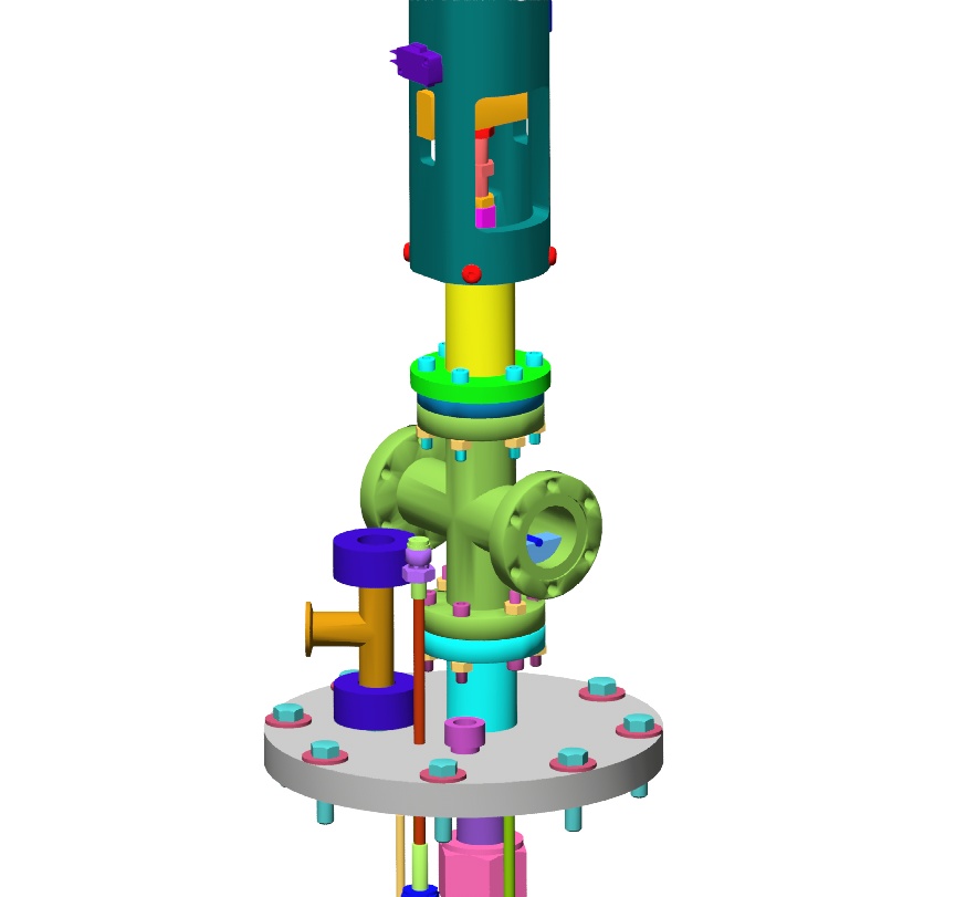
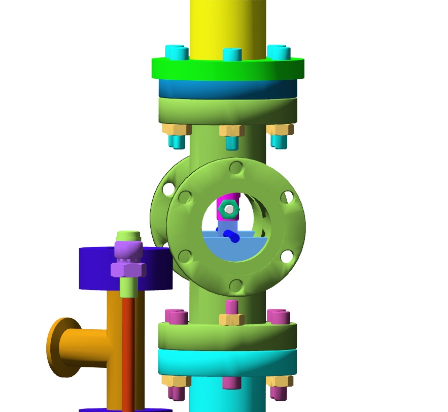
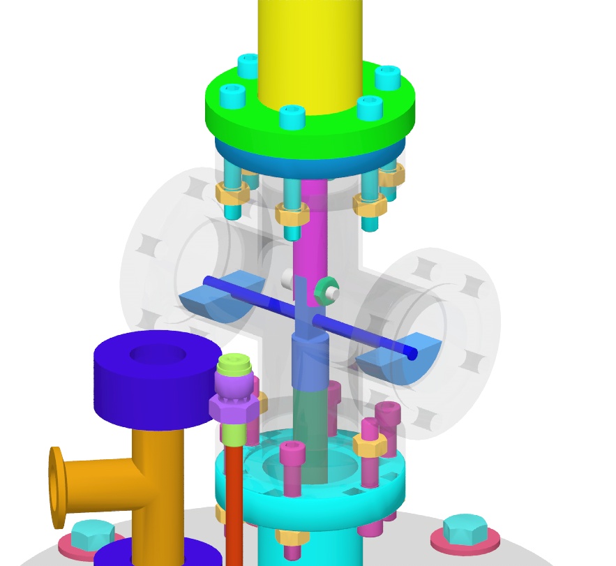
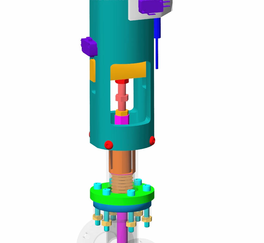
The next series of pictures show details of the construction of the top of the insert. The top flange had to be designed to allow for a variety of penetrations into the bath for instrumentation and pumping. At the very top of the insert is the G0 valve actuator. This actuator pushes on the rod that actuates the tester through a linear motion vacuum feed-through. Shown here are details of the custom designed feed-through, but the real one uses a feed-through that was already at UIUC. The blue rod shown supported on arc segment pieces is an installation fixture that holds the piston up and allows it to be connected to the shaft coming down from the actuator. Once the linkage is all connected, the blue pieces are removed.
These pictures focus on the design of the custom linear motion feed-through. The picture on the lower left has a few rendering glitches. The bronze bushing that aligns and stabilizes the actuactor rod is shown hollow. This sometimes happens with cylindrical objects that touch line-to-line in CAD models.
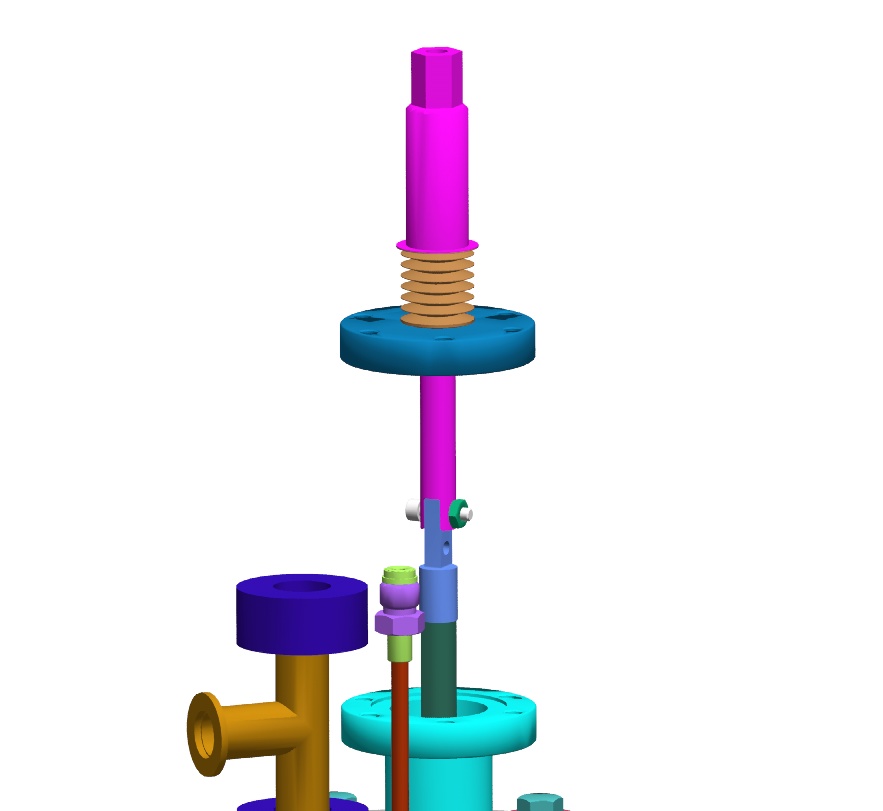
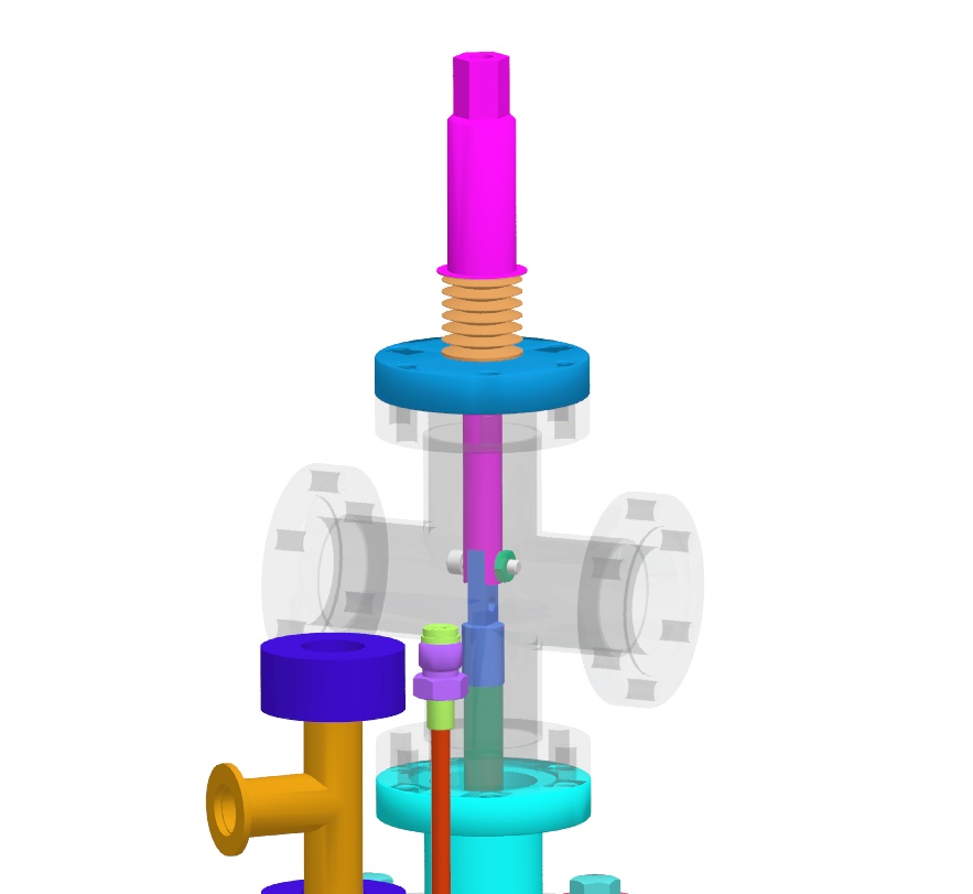
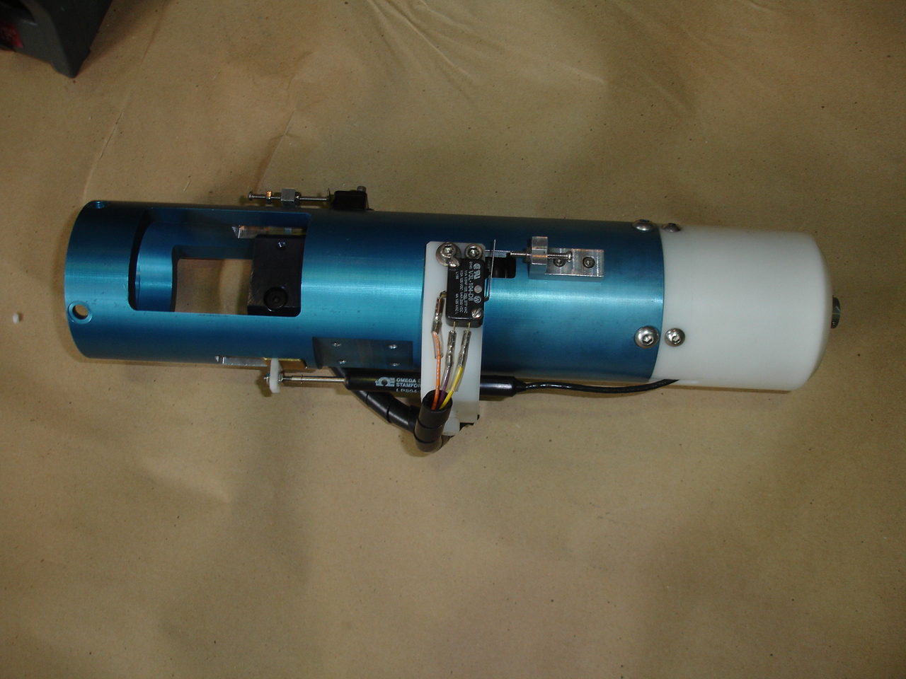
These pictures show the turnbuckle connection that joins the tester actuator rod to the G0 valve actuator, and the actuator itself. The actuator is made by Novatech.
Back to the Bartoszek Engineering Projects Page
Back to the Bartoszek Engineering Home Page
|