|
First Pass on the "Soccer Ball" Support Structure
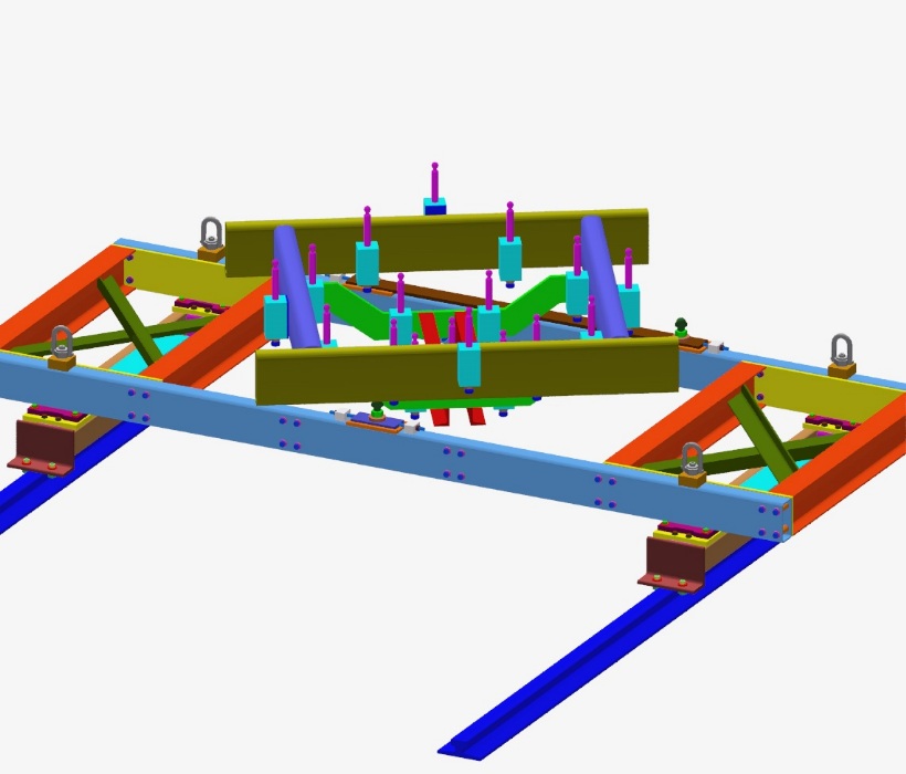
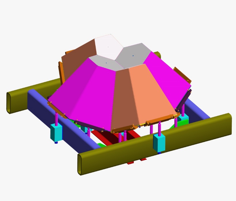
These pictures show the first pass and concept behind the soccer ball support structure. After much searching, I discovered where the patterns were that simplified fabrication of the support (made it feasible and affordable). Interestingly, the structure that most easily aligns to the soccer ball does not align at right angles to the beam line. That is why the steel shown in the first picture on top of the MuCap structure is rotated as shown. The fundamental design concept is that a ball and socket joint is the only way to connect bars whose angles are all over the map. Most conveniently, if you cut a hemispherical pocket in the center of each of the bars that connect the hex and pent cans together, the balls on top of the vertical rods engage the pocket in such a way that even at strong angles the bars should not want to pop off or disengage the rods. I also discovered that there were only eight layers where the ends of the support rods fell, simplifying the fabrication.
That said, this is not a simple structure, and this is not the final version of the structure. There are only 17 rods shown supporting the soccer ball. I determined earlier that this number was not sufficient. In the solid model, each hex and pent can has a point shown at its center of gravity (these do not render). The most fundamental criteria for holding something up is that the line dropping straight down from the CG should pass through an area surrounded by support points, and not be outside the area bounded by the support points. With only this many rods, if another layer of cans is added the CG of a can in that layer would be outside the area defined by the bars that support the can. In effect, the can would try to tip out of the incomplete soccer ball.
There will be additional bars and support rods to a higher layer of cans than is shown here. This structure is the minimum support structure necessary to mount the first two layers of cans. It's not clear to me yet whether the additional rods will be bolt-ons or part of the welded structure. The design philosophy here was driven by the difficulty of aligning cans at assembly. There are two possible design paths in any complex structure like this. The first is to make a completely bolted and shimmed structure that can be changed to adapt to any tolerance errors on the cans. The second is make a structure that has the support points machined into place with sufficient accuracy to define the structure. I am using the second approach because my thought was that if I designed a completely changeable structure, when it was delivered to PSI nobody would know how to put it together and it would require days of survey and alignment to assemble. Some of the choices have to be fixed into the structure to know where to start.
The lowest steel structure under the ball is currently imagined to be a fairly rough weldment of blocks, plates, and structural tubing but once welded together it would be put on a large enough milling machine to accurately place slip fit holes for the vertical ball-end rods. The horizontal placement of the rods is then determined by final machining of the structure. The vertical height of the rods is also determined by machining the depth of the holes in the structure, but with a caveat. The bottom of the holes in the structure is tapped for a 3/4-10 bolt. The vertical ball-end rods actually sit on a bolt that can adjust their height in the structure.
In this way, if there are tolerance problems with the cans, the rods can be adjusted. If the problems are really serious, a thought I try not to think about, the holes could be enlarged or custom rods could be made with offsets to adapt to the errors. The most brute force method of adjusting to a horizontal mis-match between a rod and socket is to just bend the rod. (Some mechanical advantage may be necessary. The rods are 1 inch in diameter with .750 diameter spherical ends.)
Click on the thumbnails to get an expanded image. You are welcome to download any of the images. If they are used for other than private viewing, credit to Bartoszek Engineering would be appreciated.
The MuCap structure will not be used on the MuLan experiment because of space limitations in the hall, but it was instructive from a scale perspective to see how these two structures fit together. We may end up using many similar pieces from MuCap so the exercise is probably not wasted. This makes clear the angular difference between the lines of the soccer ball support and the beam lines.
I do imagine having an alignment mechanism between the soccer ball support and the floor mounted structure. The adjustments talked about earlier are not for alignment to the beam-line, only for assembly of the soccer ball.
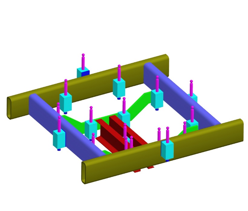
Close-up of the structure
The structural concept here is that a rectangle of structural tubing, 8 x 3 x 1/2 provides the rigid base that support points on different elevations can connect to. The finished soccer ball will weigh approximately 1100 lbs. The total number of support points is 25, making the load on each point (assuming equal distribution) 44 lbs. The load will almost certainly not be equal because as the support points move outward from the center of the base, the angles the ball-end rods make with the cans get steeper and steeper, with less of the load above outlying points. The ball-end rods can take way more load than 44 lbs, literally at least an order of magnitude more.
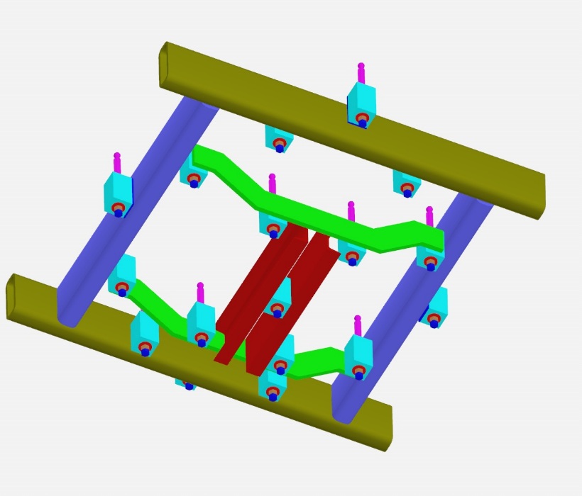
The bottom view (on the right) shows the 3/4-10 bolts with lock-nuts that do the vertical adjustment of each rod. There is a nominal +/- .25 inches of vertical height adjustment. If the cans were all perfect, one could simply let the ball-end rods sit on the bottoms of their slip-fit holes and they would be at the right elevation with respect to each other.
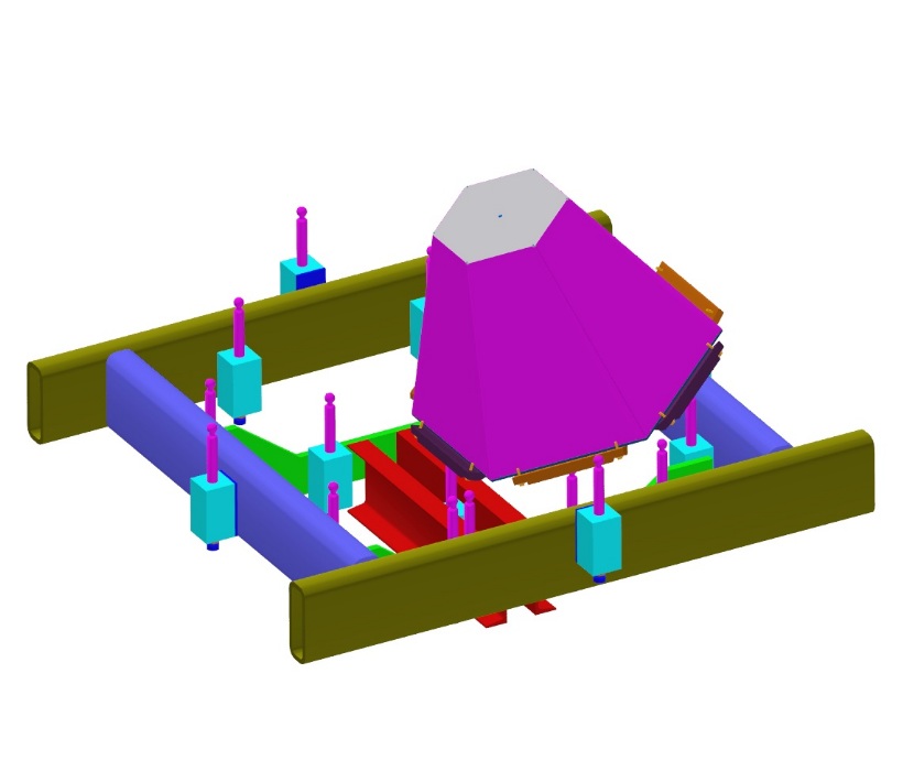
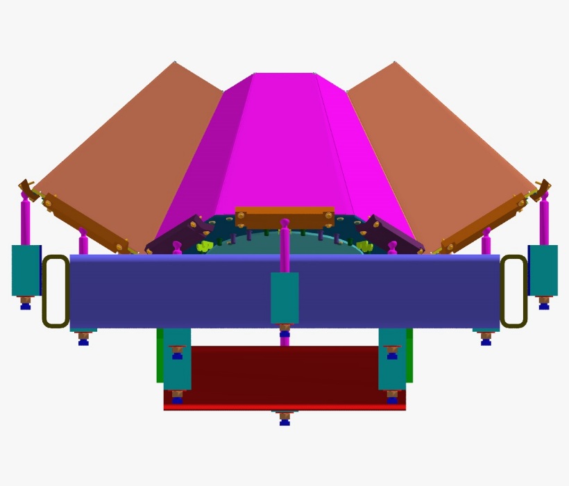
Adding the first two hex cans
In any assembly, you have to start with the first part and build up from there. The left picture shows the first hex can mounted on its ball-end rods. There should be plenty of room around the connectors to get the cables connected. There is also plenty of structure to route the cables along and strain-relieve them.
Each can must be pre-assembled with some of its support bars bolted to the lid. As cans are added they are bolted to the bars on previously assembled cans. It should be possible with the ball and socket joints to simply lower straight down each following can onto the structure.
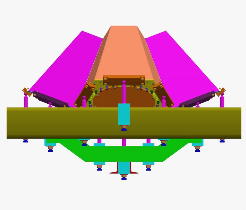
Adding the first two pent cans
Once the first two hex cans are installed, the first two pent cans attach to those. At this point the soccer ball has a stable base upon which to add all the other cans.
I will post more pictures as the rest of the stand and assembly is fleshed out.
Back to the MuLan Main Menu
Back to the Bartoszek Engineering Home Page
|