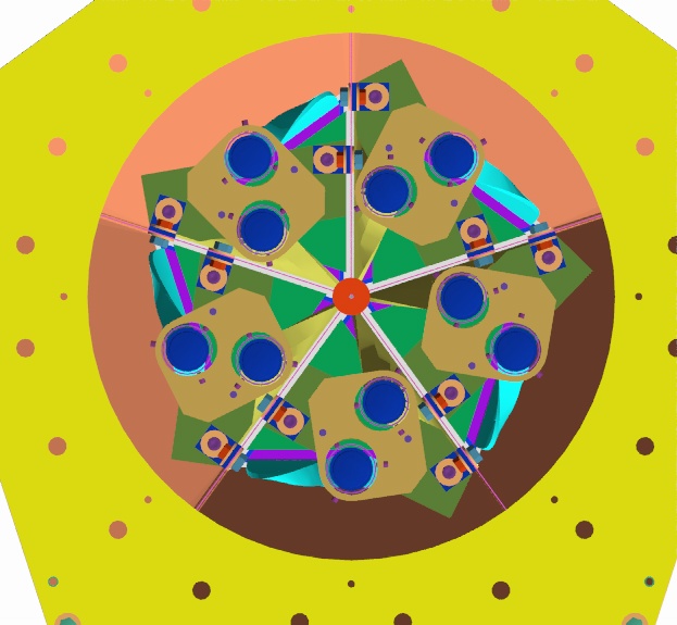
Renderings of PMT support concept 3as of 1/15/03
This re-design was prompted by the fact that the previous design did not allow enough tolerance on the location of the PMT, and the 2 set screws/PMT in the previous design did not allow for a completely arbitrary location of the PMT inside a reasonable boundary. (The two set screws would push the PMT against the inside surface of the hole.
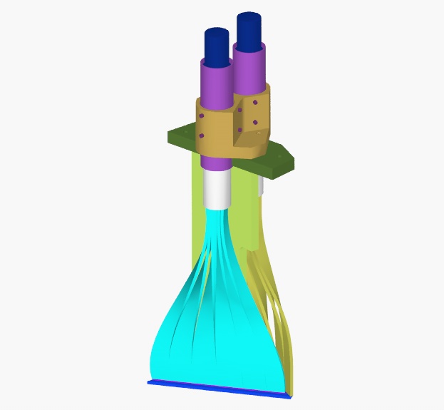
To give the PMTs maximum freedom of location and adequate restraint, I borrowed the design that worked so well in MuCap for the PMT holders. In MuCap it was possible to find an appropriate size of PVC pipe because the mu metal shields on the PMTs are larger. In this case, the closest PVC pipe that I found was too large. The PMT holder in this design is machined from a piece of PVC plate. Machining operations and datums were kept as simple as possible for minimum cost.
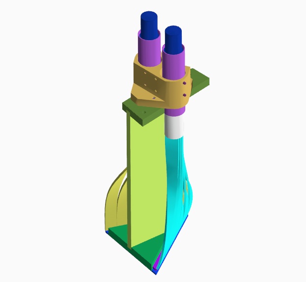
Once the PMTs were adequately supported, the new PMT holder was incompatible with the old sheet metal attachment to the ribs. By stretching the top plate on the backbone assembly, I could get two 1.5 X 1 X 1/8" aluminum angles to engage the ribs and the backbone assembly. This size aluminum angle may be available at hardware stores. It is cut to length and has two holes drilled in it. Couldn't be much simpler or cheaper.
Click on the thumbnails to get an expanded image. You are welcome to download any of the images. If they are used for other than private viewing, credit to Bartoszek Engineering would be appreciated.
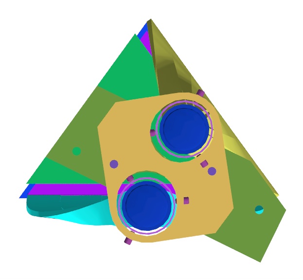
You can see from these pictures tht the top green plate on the detector backbone assembly has been extended and two tapped holes added to attach it to the ribs in the can. The top view (third picture) shows that each PMT hole in the PMT holder is slotted in the direction perpendicular to the edge of the scintillator that its light guides are glued to. This allows more variation in the direction that is harder to control during the bending of the light guides. The six set screws can control translational and angular inaccuracies of the PMT and mu metal shield assembly.
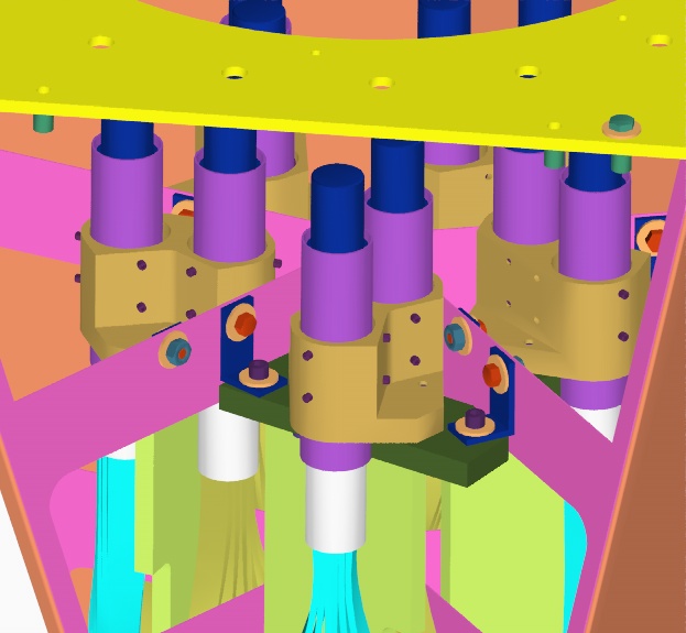
New angle brackets hold detectors in
These pictures show the new L angles that attach the detector assemblies to the ribs. Holes have been located in the ribs for the attachment bolts. The clearance holes should be large enough to allow for any tolerance build-up in the sheet metal can. The detector packages are still possible to be installed independently of each other. Socket head cap screws are used for the bolts whose heads point up, out of the opening of the can, so that Allen wrenches can be used on these. Hex head bolts are used on the rib faces so that wrench pairs are easy to insert through the opening of the can. Wing nuts are probably too big and might pose a disassembly challenge, but this can be tested.
Back to the MuLan Main Menu
Back to the Bartoszek Engineering Home Page
|