These views of the assembled soccer ball were requested at the last meeting. If there are any other views required, just send me an e-mail. The view naming conventions are a mixture of architectural and mechanical naming conventions. (I used "top" view instead of plan, but the side views are all called "elevations".) Downstream is always to the right or in the center of the picture (for the upstream elevation only).
The last two pictures illustrate some issues associated with installing and supporting the target assembly.
Click on the thumbnails to get an expanded image. You are welcome to download any of the images. If they are used for other than private viewing, credit to Bartoszek Engineering would be appreciated.
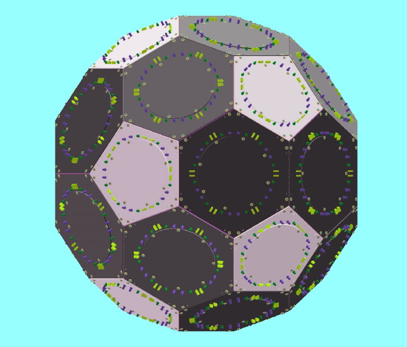
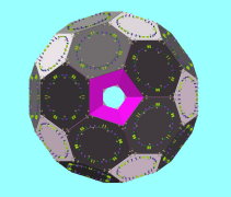
Elevation View of the Soccer Ball looking Downstream
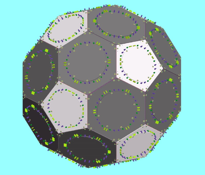
Elevation View, Downstream to the Right

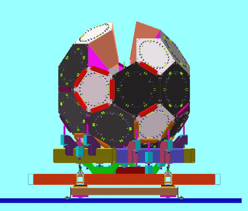
Elevation View, Downstream to the Right, Foreground Cans Removed

Top View, Downstream to the Right

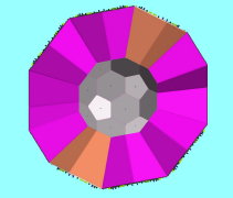
Top View, Downstream to the Right, Upper Half Cans Not Shown
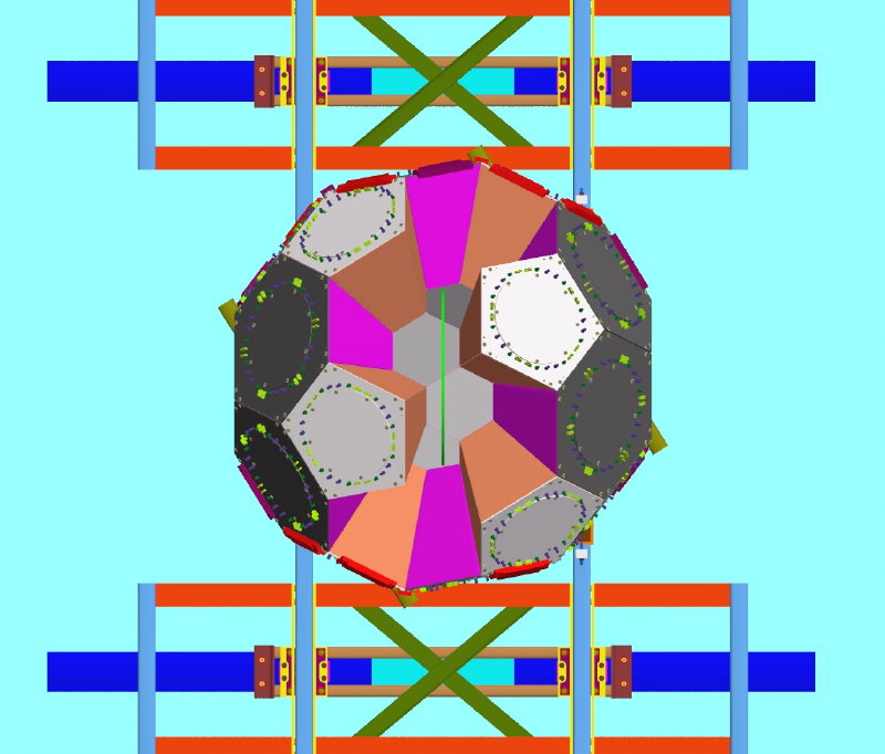
Four Top Cans Removed for Target Installation
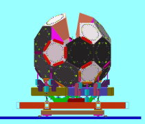
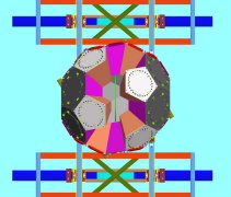
I started thinking about what the ball configuration would be when the target is likely to be installed in the final assembly. I created these two views to stimulate discussion. The green disk shown is the larger one created at the meeting which probably doesn't reflect the size of the final target assembly.
Some comments on the target and He bag:
- This configuration does not look compatible with the idea of a helium bag that is connected to the target and protrudes to the upstream pent opening. At least two more cans would have to be left out to create an opening that went all the way upstream to the upstream beam pipe opening.
- If the target ends up being much thicker than the target disk shown (.5 inch), then it looks like more cans would have to be removed.
- Cans can only be installed radially. Four cans could not be simultaneously lowered into place because each one needs to be inserted along its own axis. The top two are the only ones that might be able to slide down into place together.
- It starts to look to me that if you do not want to create a beam that rests in both the upstream and downstream beam pipe openings and contains the helium bag, target and whatever, that we will have to build a temporary support frame around the soccer ball. The purpose of this frame is to support the target assembly on wires that match up with intersections of cans that are not assembled yet. As cans are added to the assembly, the wires to the temporary frame would be attached to the cans and eventually the temporary target assembly frame could be removed. (Or maybe the target could always be hung from this surrounding scaffolding and never hang off the soccer ball.)
- The idea of a beam that can be lowered onto the bottom half of the assembled soccer ball looks to me to be the easiest one to implement and probably the cheapest. A cantilever beam from the upstream end was also suggested, but this raises questions of how to support the moment load from the cantilever. The simply supported beam would just rest on both ends of the soccer ball.
Back to the MuLan Main Menu
Back to the Bartoszek Engineering Home Page