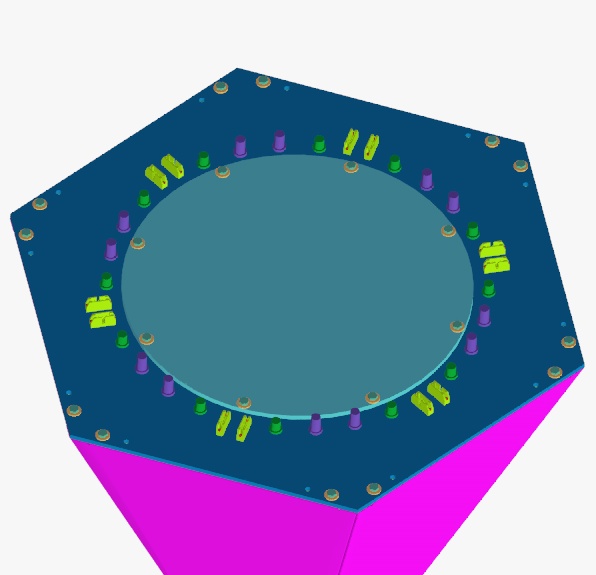
Renderings of the final 10 pin connector on the hex and pent cansas of 3/19/03
These pictures show the arrangement of the 10 pin connectors on the hex and pent cans. They have been checked with the final assembly and do fit with the support structure as currently imagined. The main questions I have are whether the relief cut on the inside of the lid under the connector is large enough. I believe the mating connector can be removed with this arrangement, but it would be nice to get confirmation from others.
I have left a minimum of .75 inches clear at the ends of the connectors on top for the attachment and use of the ejectors which are not modeled here. In the case of the pent can, you can't eject both connectors simultaneously because the latch ejectors in between connectors have to be operated in series, but this didn't look like a real problem. (Who would simultaneously release both cables anyway?)
The moment I hear that this design is OK, I will get the lids into drafting so the can manufacturing drawings can be complete.
Click on the thumbnails to get an expanded image. You are welcome to download any of the images. If they are used for other than private viewing, credit to Bartoszek Engineering would be appreciated.
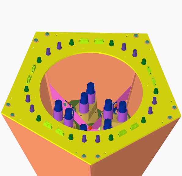
These pictures show close-ups of the connectors from top and bottom of the fixed lid, and what the relief looks like on the bottom side. The lid is .125 inches thick directly under the connector. There is additional clearance for the mating connector at the ends of the thru slot (not the blind slot that has semi-circular ends,) to allow room for the radii at the slot ends. (This is to simplify manufacturing of the lids by allowing a single milling operation to make the thru slots.)
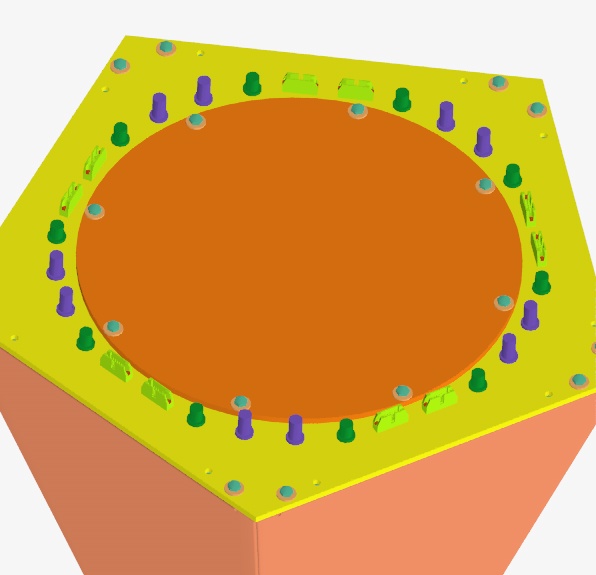
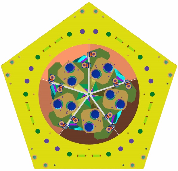
Pent Can connector mounting
The pent can arrangement had to be different from the hex cans because of the greatly reduced amount of area on the pent lid. The hex can lids have the SHV and BNC connectors equally spaced around the removable lid as if there were 30 connectors all together, but there are 6 positions missing in the middle of each bay in the pattern. These middle positions are taken up by the two 10 pin connectors.
In the case of the pents, the SHV and BNC connectors are closer together than they would be if I had followed the hex lid pattern because the latch ejectors on the 10 pin connectors need more room. I think every connector has sufficient room in this arrangement and the 10 pin connectors are clear of the support structure.
Back to the MuLan Main Menu
Back to the Bartoszek Engineering Home Page
|