Renderings of the MiniBooNE Horn Water System DesignImages on this page focus on the design of the water system that spray cools the inner conductor of the horn, and takes the water that drains out the bottom of the horn to be recirculated in the RAW system. If anyone would like to see a closer view of any component, or a different rotation, just e-mail me. Same for any comments or questions. At this point, the next things to do are connect the water support frame to the containment box, design plumbing anchors and supports, and begin to work on the fiducials needed for alignment. The horn support from the containment box also needs to be redone from previous pictures now that the water system is defined. You are welcome to download any of the images. If they are used for other than private viewing, credit to Bartoszek Engineering would be appreciated.
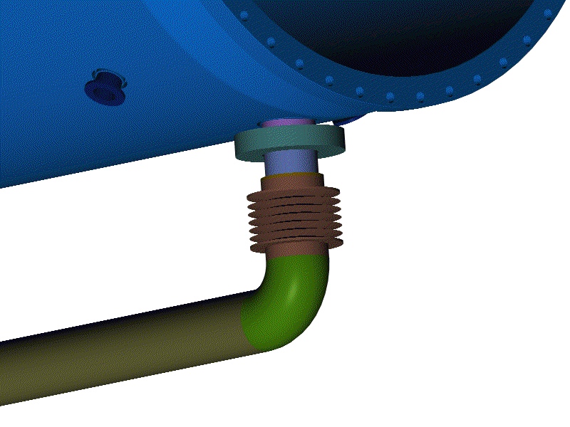
Pipe is 2" Schedule 40 with Flowline butt weld fittings. Bellows is from Standard Welded Bellows. All materials are stainless steel.
The bellows are all modeled just for illustrative purposes. The actual number of convolutions is higher.
The brown blocks in this view are custom elbows that I would like to make from S.S. They get the water from the manifold to the nozzle, and they also have tapped holes to attach the bars that align the water nozzles.
This view makes everything transparent except the nozzle, its feed tube, and the elbow block. The nozzles have good clearance all around them to the horn so that the horn will not transmit vibration to them except through the bellows.
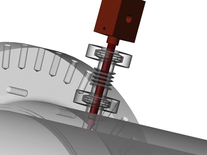
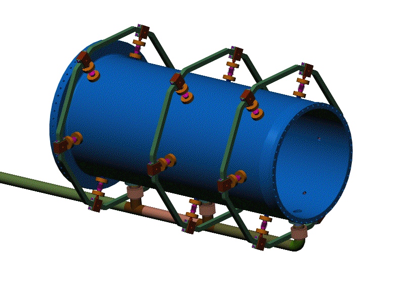
This view shows the nozzle alignment arms assembled to the elbow blocks. These pieces are needed because the nozzles are not attached to the horn except through a bellows, so the nozzles need a separate alignment and support structure. This separation should prevent horn vibrations from fatiguing the water pipes. These bars are cut from 1" thick aluminum plate. They are designed this way for two reasons: 1) they need to be solid at bolted joints to prevent crushing; and 2) this shape would probably be more expensive to fabricate out of multiple pieces welded together than just cutting it out of a plate.
The brown bars added in this view stabilize the three planes of nozzles and alignment bars. This framework is attached to the horn box at the bottom, but I haven't done that connection yet. These bars are weldments of square aluminum tubing (1" square by 1/8" wall,) and plates to make the bolt flanges, so the amount of metal in them is reduced.
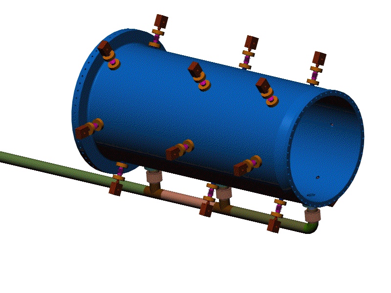
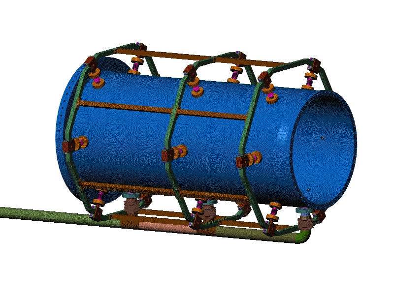
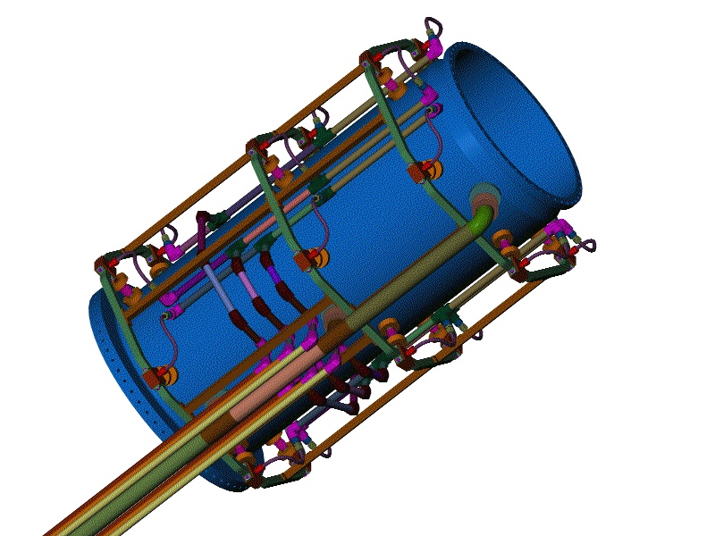
This is a top isometric view of the horn with its water supply and drain piping. It has been designed for testing in MI8, but the system would only be slightly modified to use in the target hall, if at all. The bent tubing is .500" OD x .065" wall. It is designed such that any nozzle can be removed by removing the four screws that connect it to its alignment arms, loosening the Parker fitting connecting the 1/2" tube to the 1" tubing, and releasing the outer NW25 EVAC chain clamp on the bellows. The 1/2" tube, nozzle and elbow block can then be removed radially. The 1" tubing is connected together with Parker socket weld fittings (Weld-lok series). 1/2" tube connections are made with A-lok tube fittings and Tube-to-welded system transitions. My intent was to design a system that would be easy to fabricate, welded for tightness and reliability, and made from materials that should be thick enough to have no trouble with fatigue.
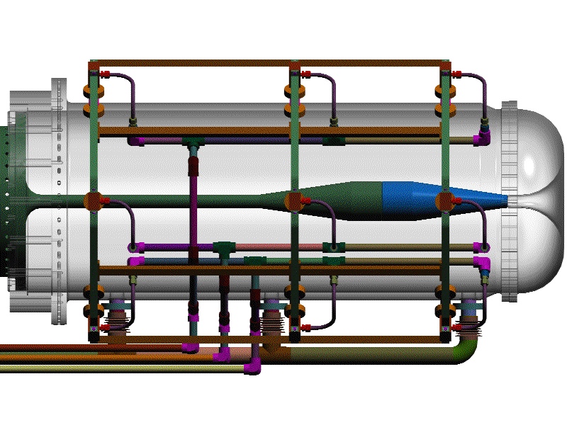
No interferences between drain and supply piping are visible here. (There aren't any.)
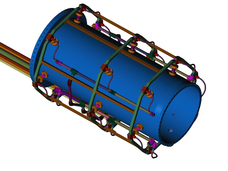
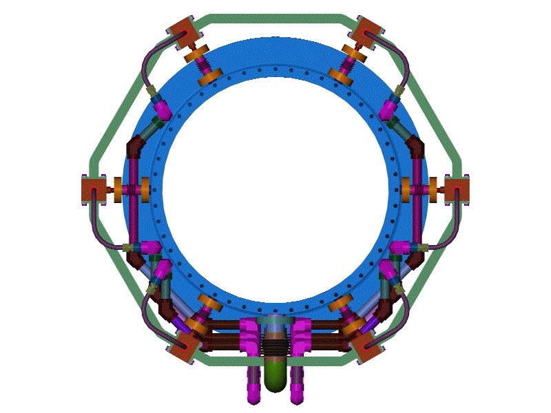
This view shows the 1" supply tubes that carry water into the nozzle system from the RAW system. The three manifold pipes on each side of the drain are designed to be assembled bottom up. They will need to be pre-assembled before the horn is lowered into the box. For testing in MI8, the system is designed to have all six rows of nozzles fed individually from their own supply pipes. We will be able to test different flow combinations by adjusting the flow through any of the six independent manifolds.
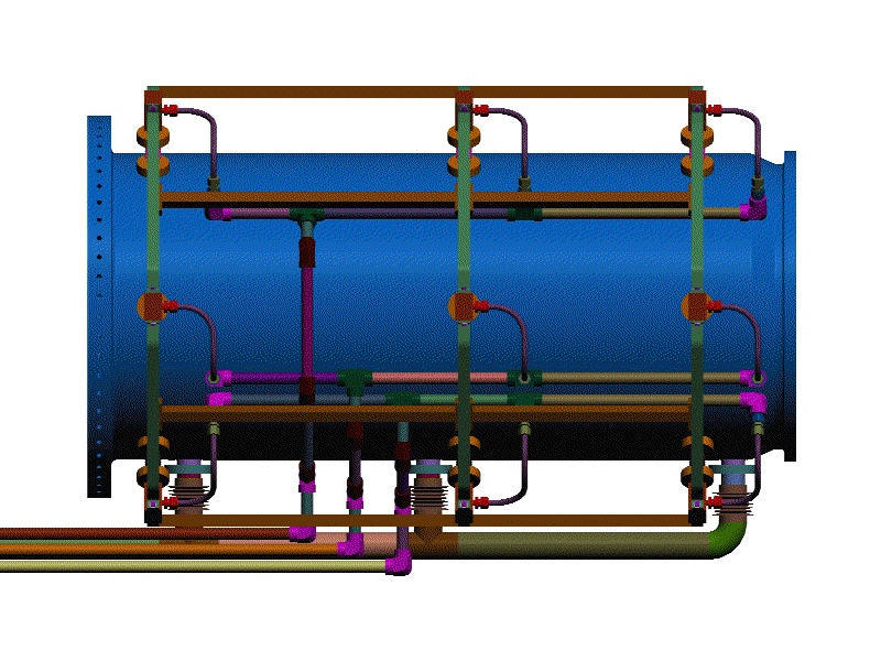
This view makes it easy to see how the elbow blocks and 1/2" tubing get removed radially. As long as the tube fitting close to the horn is parallel to its nozzle tube, it will move outward with the nozzle tube at disassembly. The system is designed so that once the 1/2" stainless tubes are formed they do not need to be bent again to install or disassemble the nozzles in the event that we decide to vary the nozzle type.
I created this view to see if the water system interfered significantly with the ports for spiders (if there will be any). I am confident that I can get the spiders in without too much trouble if need be.
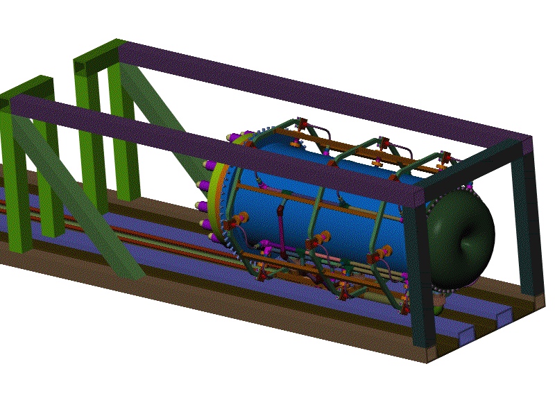
This view is just a quick check to see that the water system doesn't violate the containment box. So far so good. More detail will follow as the box evolves.
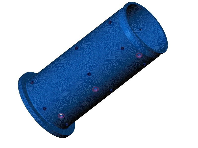
This view shows what the supply and drain ports look like from inside the horn. The only way to get this view in real life is to fish a fiber optic camera through a nozzle port. Test your friends by asking them to identify what this picture is!
Back to the Horn Renderings Main Menu
Back to the MiniBooNE Horn Main Menu
Back to the Bartoszek Engineering Home Page
|