Status of Test Fits and Fixturesas of 4/09/01
This page shows the test fits of the lower stripline, the assembly of the outer conductor onto the horn box, and the testing of the ceramic ring handling fixture. We ironed out a number of bugs in the horn box assembly and are now ready to do the actual assembly of the horn onto the horn box. The first stage of water system assembly is done and will not be redone. The striplines went together well. We made a simple modification to one edge of two ground plates and are adding tubes to hide some sharp edges on the threaded rods. The pieces of the stripline will be sent out for silver plating the week of 4/09/01 or 4/16/01. The half shells and twist transitions have already been plated and are ready to go.
Click on any of the thumbnails to get an enlarged view. You are welcome to download any of the images. If they are used for other than private viewing, credit to Bartoszek Engineering would be appreciated.
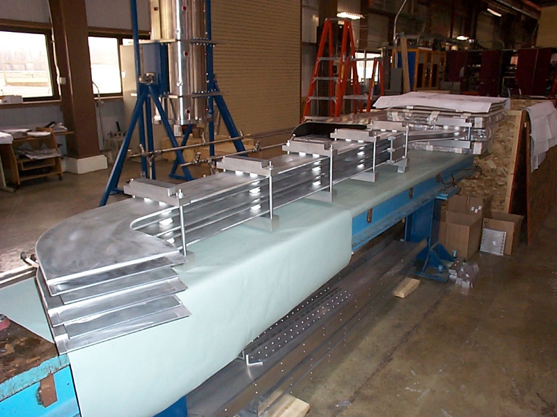
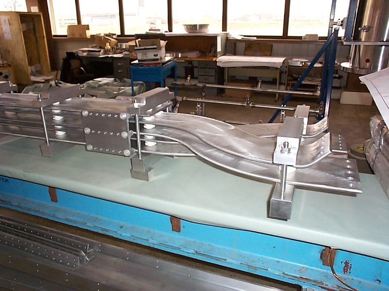
The stripline test assembly
The first image shows the offsets between the clamping ends of the stripline plates caused by welding deformations. This was caused by making the ends close to size prior to welding (because of the stock size) and then having to machine the clamp surfaces correctly after welding. We will make the next set of striplines by welding an oversize end piece onto the straight section and machining the entire final shape of the end after welding. In general, everything assembled quite well.
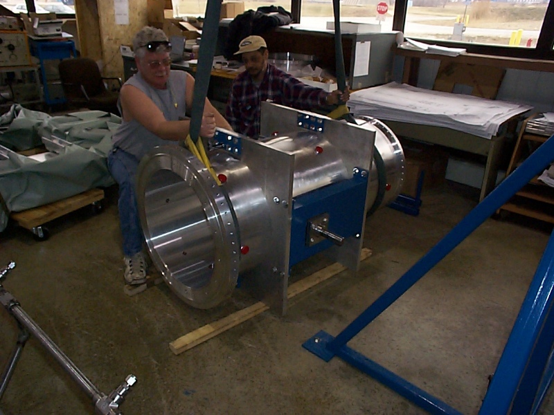
Crane Handling the OC
We took the OC off the rotating fixture to test assemble it onto the horn box. This allowed us to work out a process for crane handling, and for alignning the horn vertical in roll. We have to get the roll right to cause all of the water ports to line up correctly with the drain manifold and supply truss.
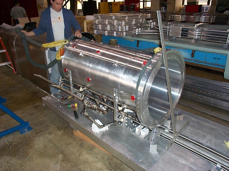
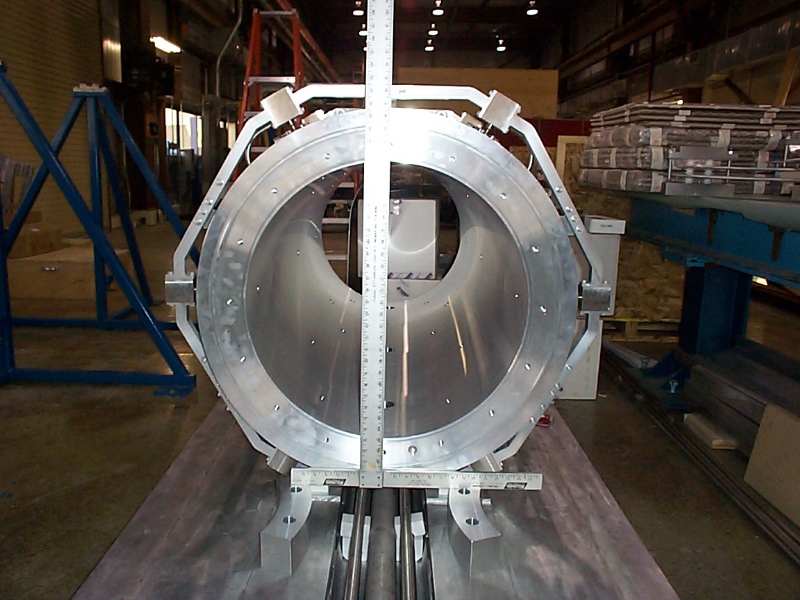
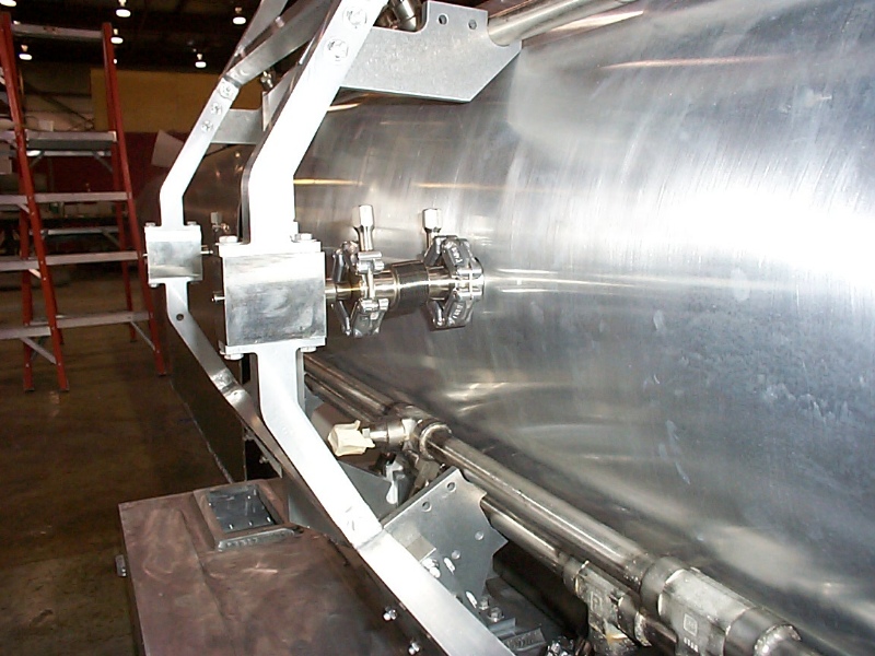
The OC mounted on its ceramics
The T square shows how well we were able to roll the OC. This will be a little trickier on the fully assembled horn because we won't be able to use exactly the same bolt holes to rotate, but the process will be very similar. Chamfering and greasing the support ceramics helped a great deal in the rotating.
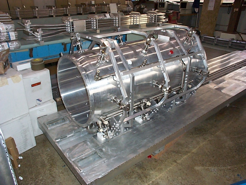
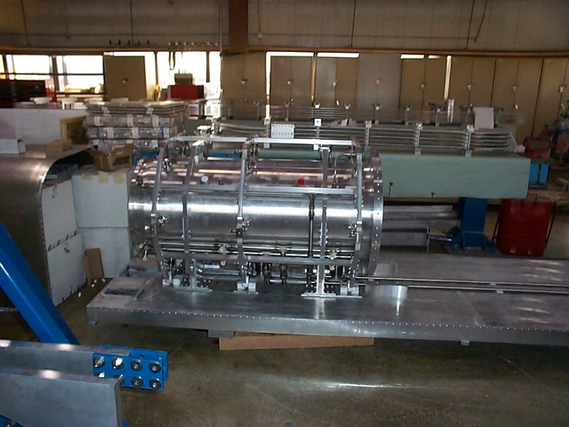
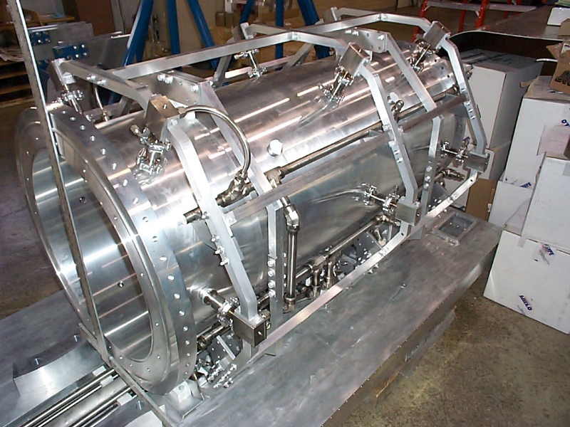
The water truss mounted around the OC
The key design concept in the MiniBooNE water system is to vibration isolate the water system from the pounding of the horn. This is accomplished by independently supporting the supply and drain from a truss surrounding the horn, and making the water-tight connections with the outer conductor with a welded bellows.
Details of the drain pipe bellows
The second picture shows that the downstream bellows is a little more compressed than intended, but it will still work. This is probably caused by a larger radius in the elbow than designed. We will follow up on this discrepancy for the next horn.
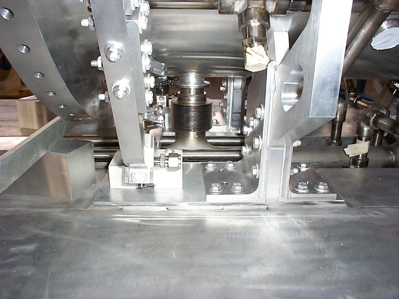
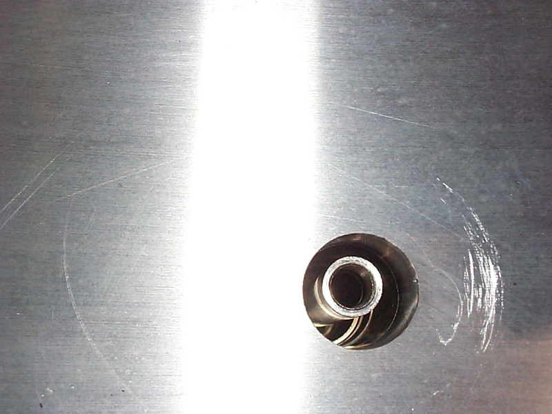
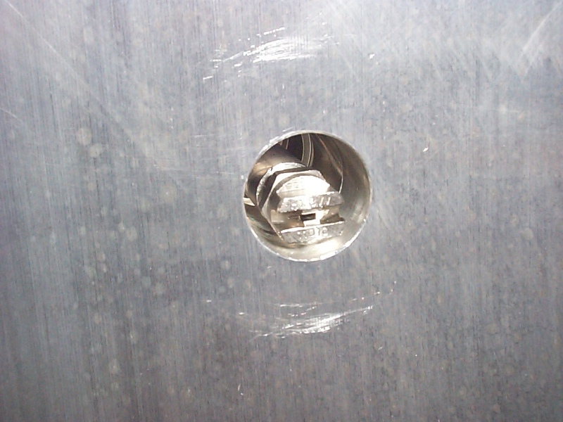
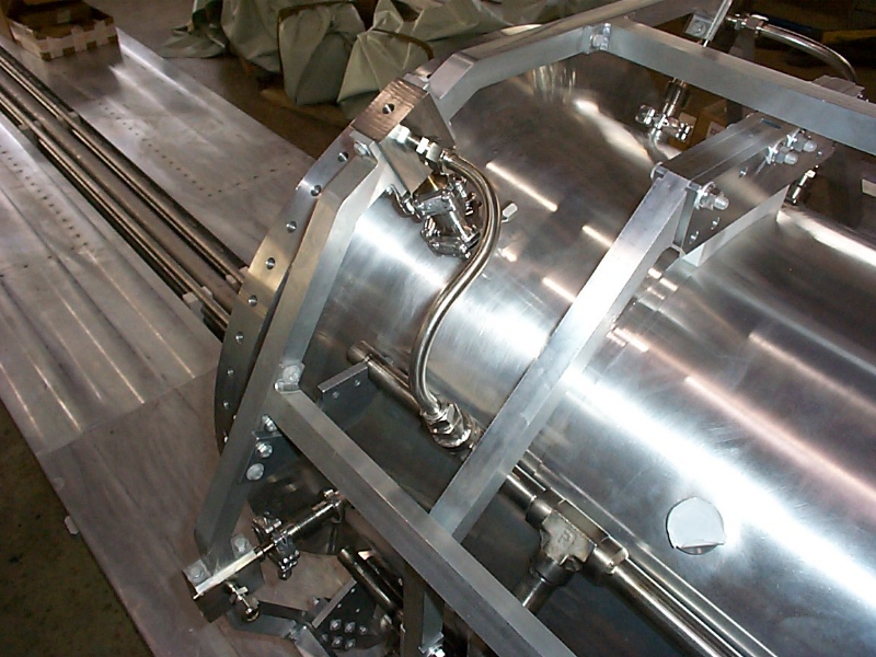
Positioning of the water spray nozzles wrt the OC
These pictures show how well the nozzles are centered in their openings on the OC. We will fine tune these a bit during final assembly, but they are perfectly fine with the offsets shown. It would be a good idea to take pictures of the water spray to make sure the nozzles point at the inner conductor. This is almost impossible to predict just from tube and nozzle placements because of variations in the spray coming from the nozzle orifice.
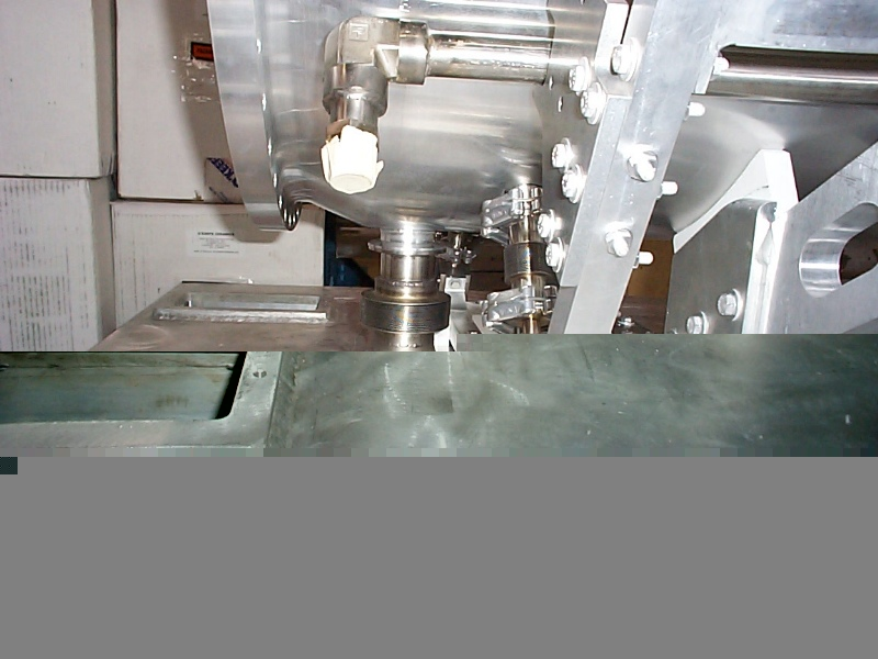
The vibration isolation bellows on the water spray nozzles
A smaller bellows is used to isolate the supply nozzles. The close-up on the left shows how water goes from the supply manifolds through the corner elbow blocks and into the nozzle tubes inside the bellows. You can see a small offset in the picture on the right. This is within the limits of acceptable variation.
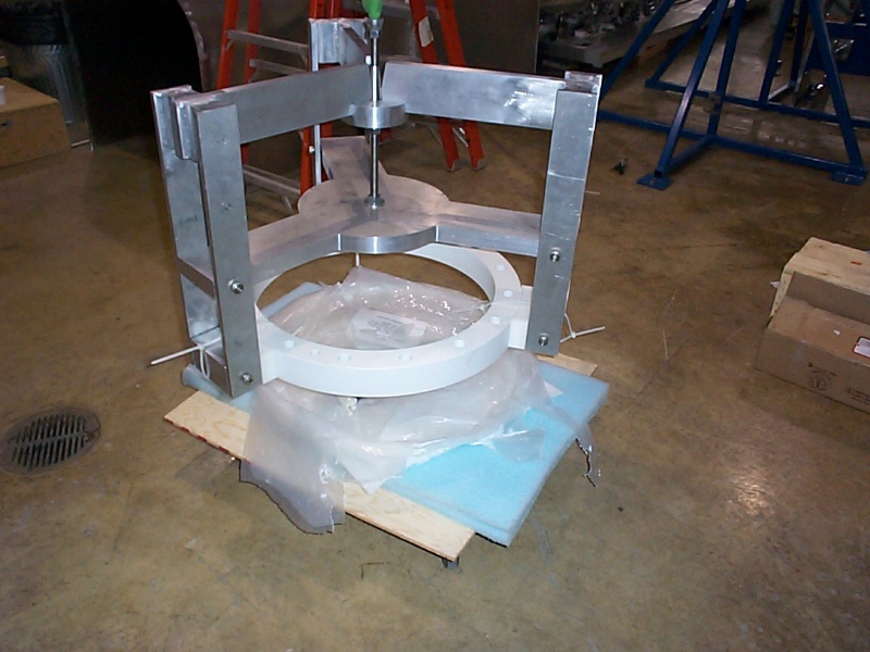
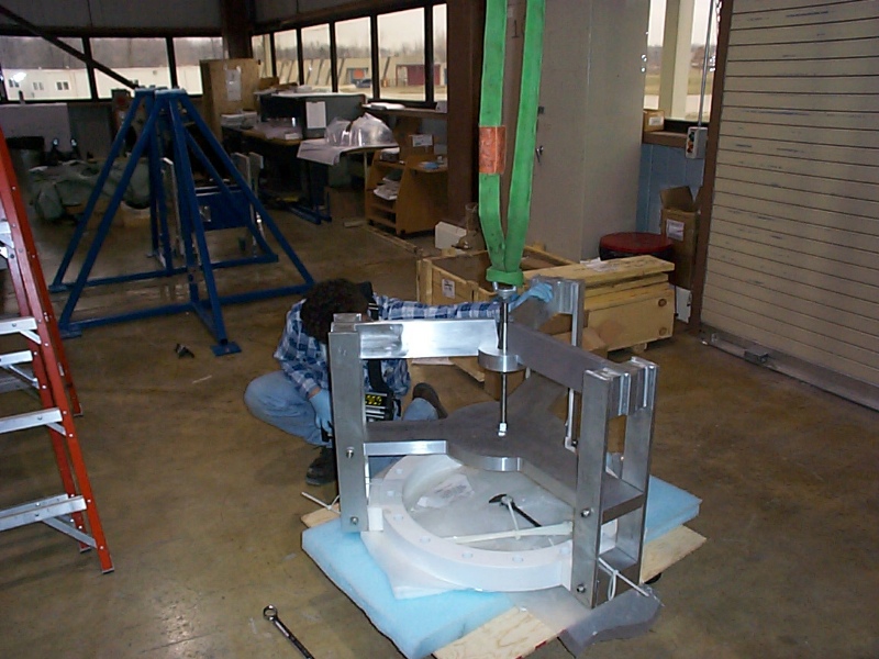
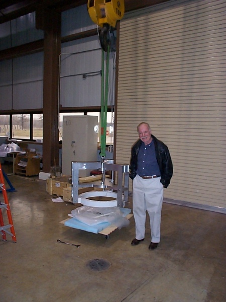
Lifting the ceramic ring with its handling fixture
These pictures show the test lift of the ceramic ring. The ceramic ring costed a lot and has a very long lead time for replacement, so we wanted to make sure we had a completely safe way to lift it from the floor to the top of the OC when it is mounted on the rotating fixture. It takes very little torque (~15 lb-in) on the 3/4-10 nut to tighten the clamp enough to lift the ring. The cable ties act as safety straps and will be cut off just before lowering the ceramic onto the outer conductor. Gerry Garvey was visiting during the lift and adds scale to the last picture.
Back to the MiniBooNE Horn Main Menu
Back to the Bartoszek Engineering Home Page
|