Test fitting the Water System Components on the Horn Box at MI-8,(Work done up to 1/26/01)
This file is intended to be an archive of pictures to show the collaboration progress on the assembly of the MiniBooNE horn, and a source of notes and guidance during the actual assembly process. The test fit of sub-systems has been invaluable in that we have discovered key components like ceramic blocks that were missing due to insufficient quantities ordered. Getting these parts ordered now while we are still getting ready to weld the inner conductor greatly improves our chances of getting them by the time we need them.
Click on any of the thumbnails to get an enlarged view.
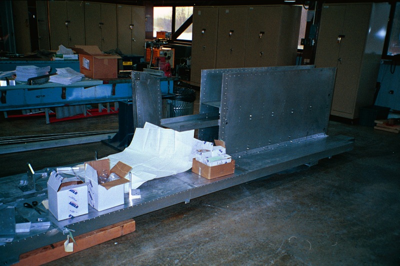
These photos show how we disassembled the horn box as soon as it was received from Viking. See the horn box at Viking page for how it looked fully assembled. We were pleasantly surprised at how stiff the side panels were only attached to the horn box by the bottom angles. We also discovered that the removal of the channels between side plates was very easy and hopefully will go in reverse just as well as we build everything back up again.
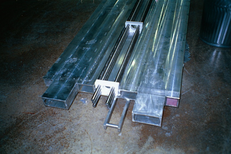
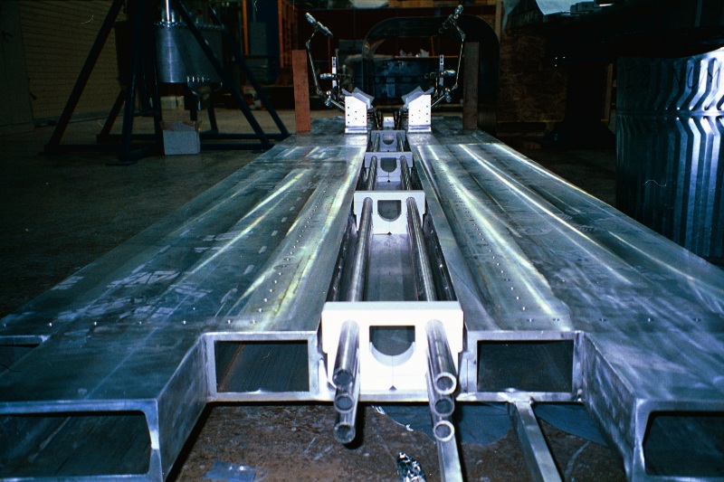
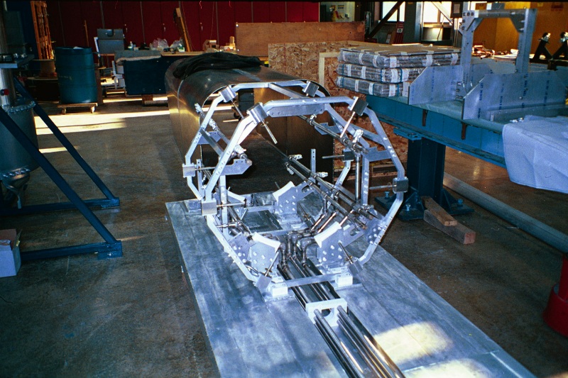
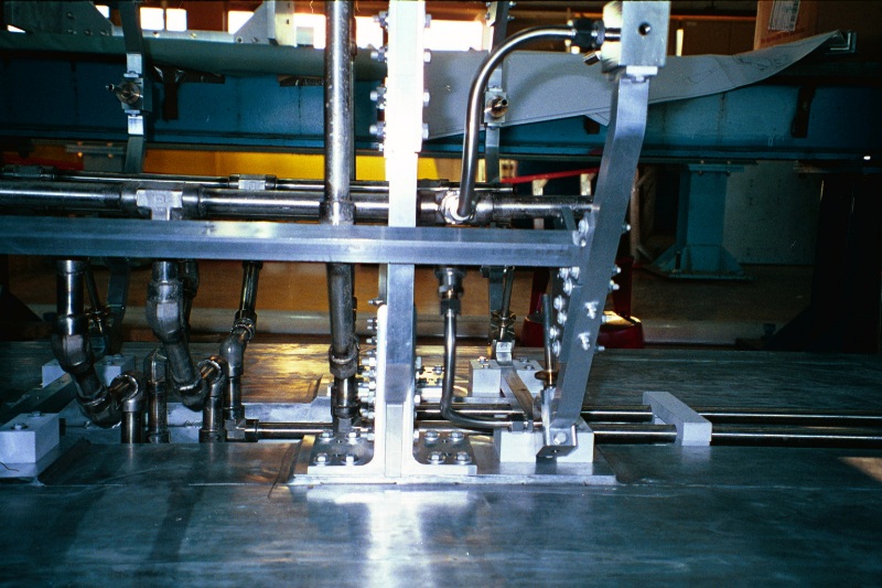
The first step in assembling the horn module is to place the water supply and drain manifolds into the trough at the bottom middle of the horn platform and stack the ceramic blocks that keep them voltage isolated from the platform. The drain manifold was not here for this step because it was in the weld shop being modified. The ceramic blocks fit the trough and the tubes perfectly. The top-most pair of supply manifolds are designed to open out for installation of the outer conductor, and so had to be temporarily supported by the 4x4s until the brackets holding the isolation ceramics can be fastened down to the platform.
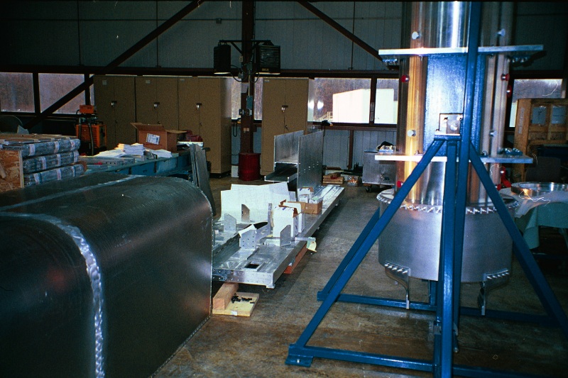
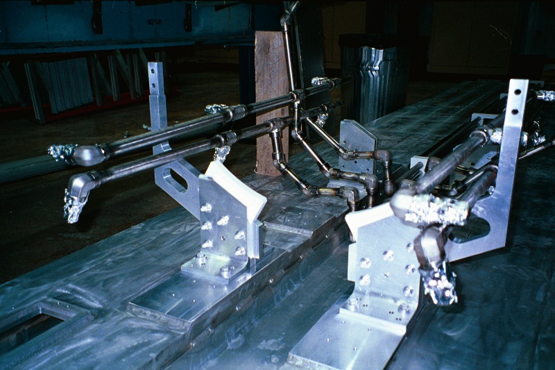
The next step is to assemble the brackets that support the outer conductor. The outer conductor is also isolated from the platform because it is likely to have a voltage difference to ground during pulsing.
The next step is to assemble the truss that supports and aligns the water nozzles. The water nozzles in the MiniBooNE horn are not rigidly connected to the outer conductor as in NuMI and most other pressurized water cooled designs. They are separated vibrationally from the OC by stainless welded bellows which offer no support, so the nozzles must be supported and aligned by their own structure. This structure, referred to as the "water truss," is also voltage isolated from the horn box platform by alumina ceramics.
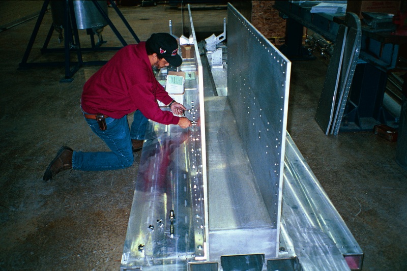
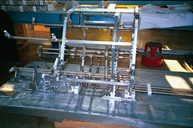
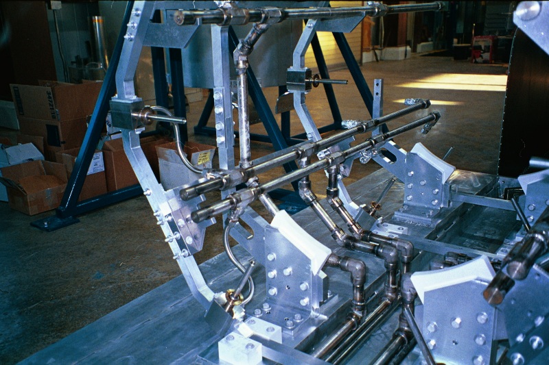
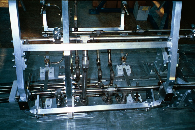
The photo on the right features the brackets that support the water manifold tubes (missing the final hold-down parts). Only two of the three support rings of the truss were assembled at this point because it was here that we discovered the shortage of truss isolation ceramics. We are making aluminum dummy blocks to continue the assembly which will be changed out when the ceramics arrive.
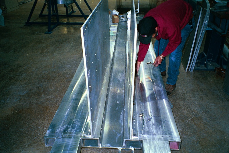
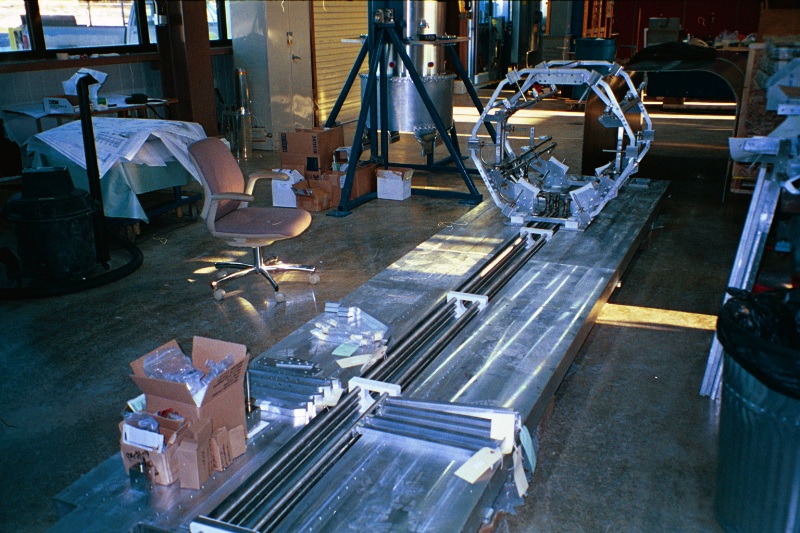
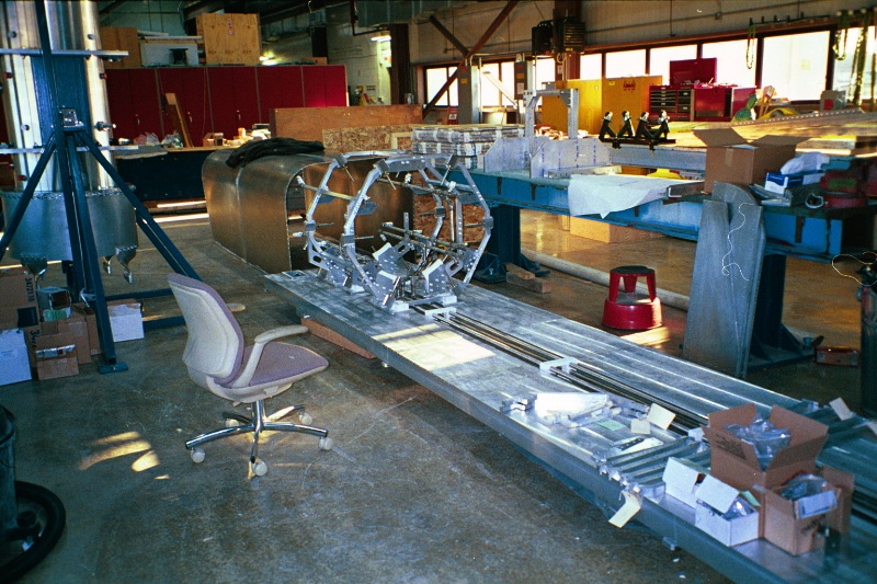
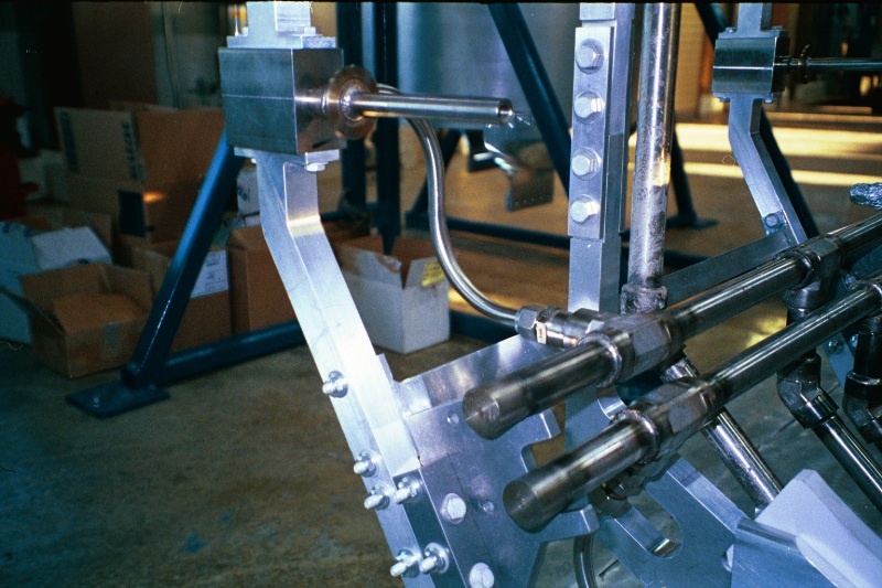
These photos show various angles and zooms on features.
Back to the MiniBooNE Horn Main Menu
Back to the Bartoszek Engineering Home Page
|