Pictures of the MiniBooNE Horn Spider Design,updated 11/2/03The pictures on this page show the design of the "spiders" that were intended to laterally brace the inner conductor from the outer conductor while voltage isolating the two. We assembled the horn without spiders to begin our prototype testing, and made displacement and frequency measurements to determine if they were necessary. The horn as of this writing has withstood over 50 million pulses and shows no sign of a problem with excessive vibrational amplitude of the inner conductor during pulsing. We built these pieces, but they were never used in the horn. Please stop using pictures of the horn that show the spiders in public presentations. This page is here as a record of the design but I want to make it clear that our horn has no spiders. Click on the thumbnails to get an expanded image. You are welcome to download any of the images. If they are used for other than private viewing, credit to Bartoszek Engineering would be appreciated.
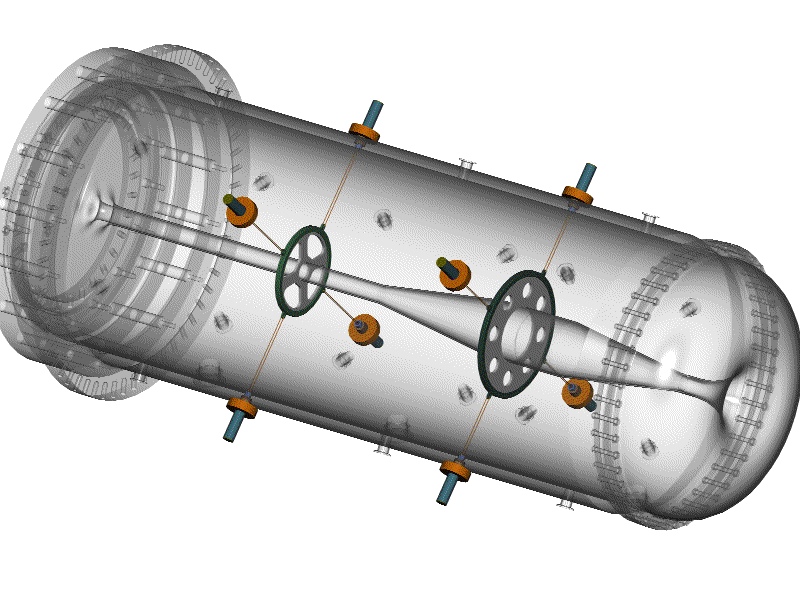
This picture shows the design of the spiders, the lateral bracing between the outer and inner conductors. The concept is that the ceramic around the inner conductor holds off the voltage of the inner conductor from the stainless aircraft cable that braces it. The cables are all adjustable from outside the outer conductor so centering of the inner conductor could be done if necessary or desirable. Another very positive feature of this design is that any differential axial motion between the inner conductor and outer conductor is accomodated by the fact that the cables have almost no stiffness out of plane, and the inner conductor is free to slide within the hole in the ceramic disks. The cables would also be very poor transmission lines for vibrations between the inner and outer conductors.
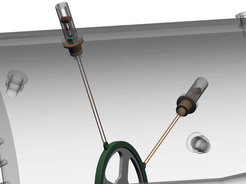
This view shows how the stainless aircraft cable loops through the eyes on the aluminum rim around the ceramics. The cable terminates outside the outer conductor in two loops which are supported from a pin. The radial distance of the pin axis can be adjusted and locked down.
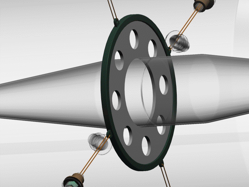
The downstream spider is designed the same way as the upstream.
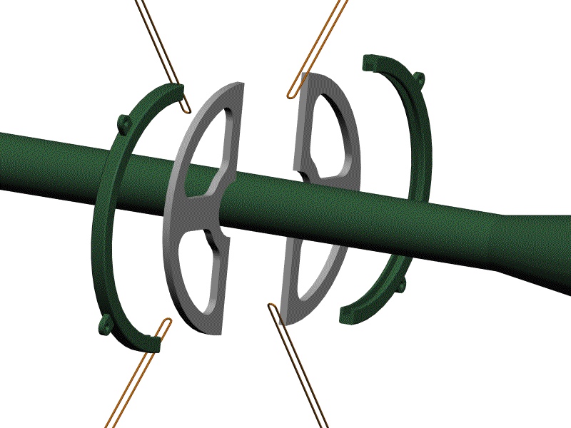
This view shows how the ceramics and aluminum rims get assembled around the inner conductor. The ceramics and rims are made in two halves. First the ceramics are assembled around the inner conductor, then the rims are assembled around the ceramics. The rims are then welded together. This design uses the ceramic in compression only, the mode that ceramic works best in. The aluminum takes all the tensile stresses from the cables. Material has been removed from the ceramic in the region where the aluminum ring would be expected to pull away from the ceramic, and the spokes are placed to absorb the corresponding compression from the aluminum rim.
The downstream spider is assembled the same way that the upstream one is. One of the advantages of this design is that there are no features on the inner conductor that have to line up with features on the outer conductor during all the welding and bolting operations of assembly. The spiders will find there "home" position as soon as the cables are tensioned because the ceramic is free to move axially and rotationally around the inner conductor.
The blue rod in this picture has a .625-18 thread on its outer diameter which engages with the light green nut. The transparent outer shell serves two purposes: water tightness and it has locking features that keep the nut from loosening. The brown pin with the grooves relieved in it for the cables is resting in a larger groove in the threaded tube, but it is completely free to move around and find its resting position in the groove.
This view makes the threaded tube transparent so you can see how the cables are routed through the center hole in the threaded tube. The cables are cut to length and terminated with stainless wire rope grommets after the inner conductor is installed in the outer conductor.
This view shows the broached features just inside the spider cap that engage the hex of the adjusting nut. The spider cap is an infinitely adjustable lock that clamps on the adjusting nut when the chain clamp (not shown) is tightened to make up the water seal. The cyan ring in the picture is the EVAC aluminum vacuum seal used a water seal in this design. The port is a standard NW25 fitting. The view also shows the pilot on the bottom of the adjusting nut that mates with a couterbored groove in the NW25 port on the outer conductor. This keeps the nut from moving from side to side during adjustment.
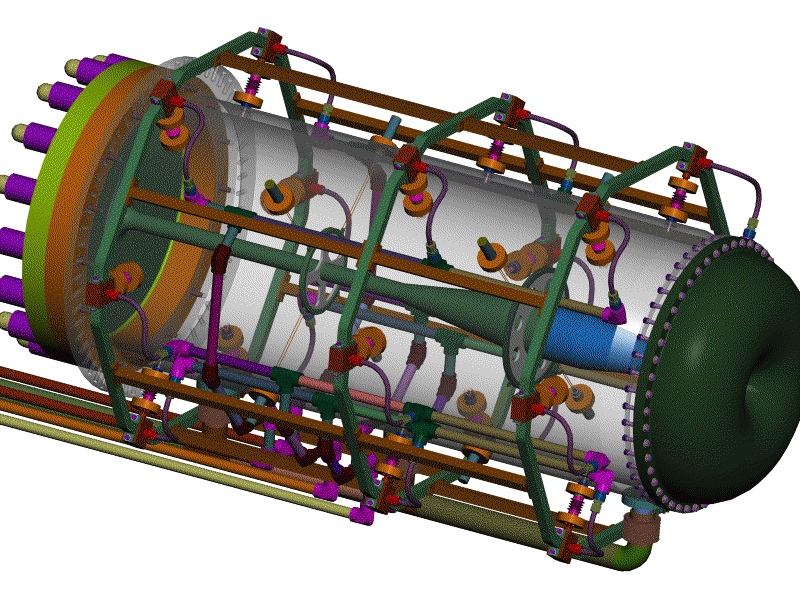
This view shows how everything fits together by making the outer conductor transparent. Back to the Horn Renderings Main Menu Back to the MiniBooNE Horn Main Menu Back to the Bartoszek Engineering Home Page |