The Installation of the Inner Conductor into the Outer Conductor, 4/13/01The inner conductor is now safely and successfully installed in the outer conductor. The operation went relatively smoothly except for a couple of Friday the 13th type "gotchas". As far as I know, we didn't hurt the inner conductor during the handling and installation, and all the fixtures worked well. Click on any of the thumbnails to get an enlarged view. You are welcome to download any of the images. If they are used for other than private viewing, credit to Bartoszek Engineering would be appreciated.
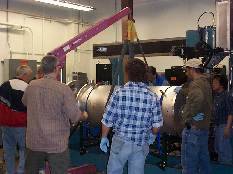
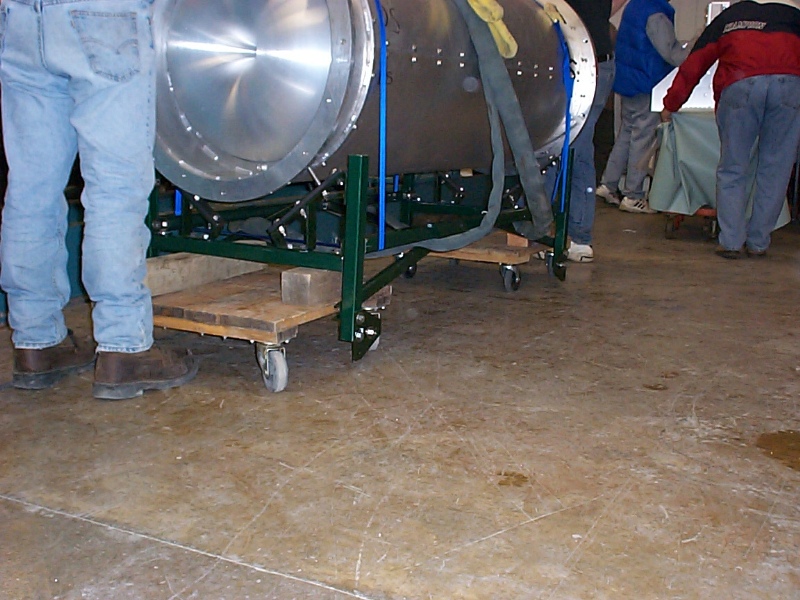
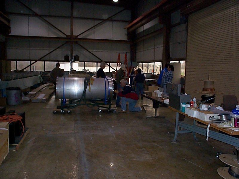
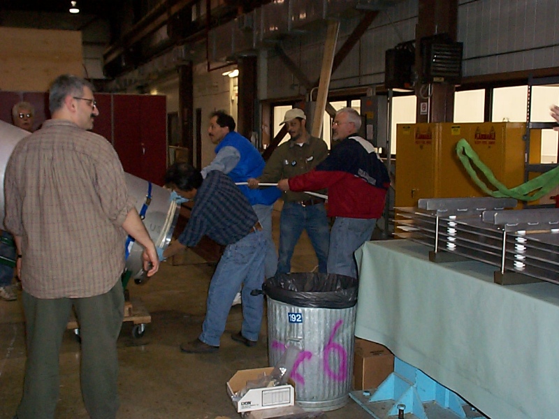
Getting the IC off the welding machine
We used the lifting hoist with slings around the bottom of the unistrut carriage to lift the IC and fixture off the welding machine. It was placed on two four-wheel dollies for rolling into the next room.
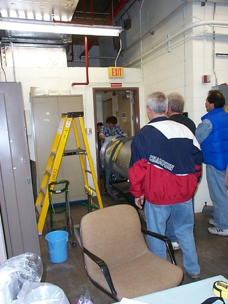
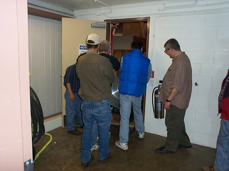
Moving the IC from the welding room to the main room at MI-8
We had some discussion about the best way to get the IC into the main room, but the direct route through the double doors worked out fine.
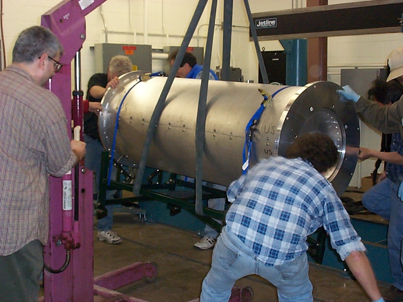
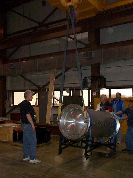
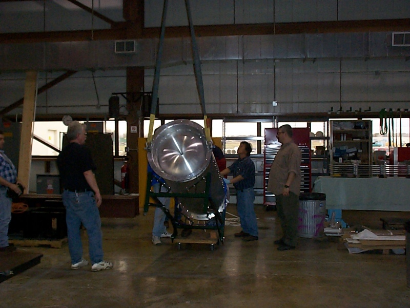
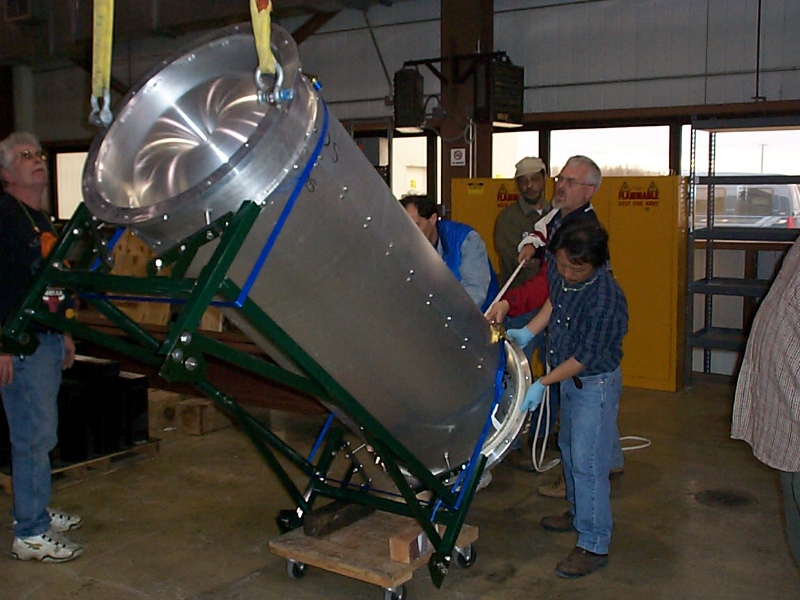
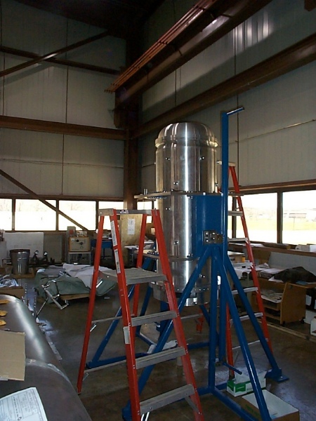
Rotating the IC from horizontal to vertical
This rotation went very easily. We restrained the whole fixture from flipping through the vertical position and went slowly and smoothly.
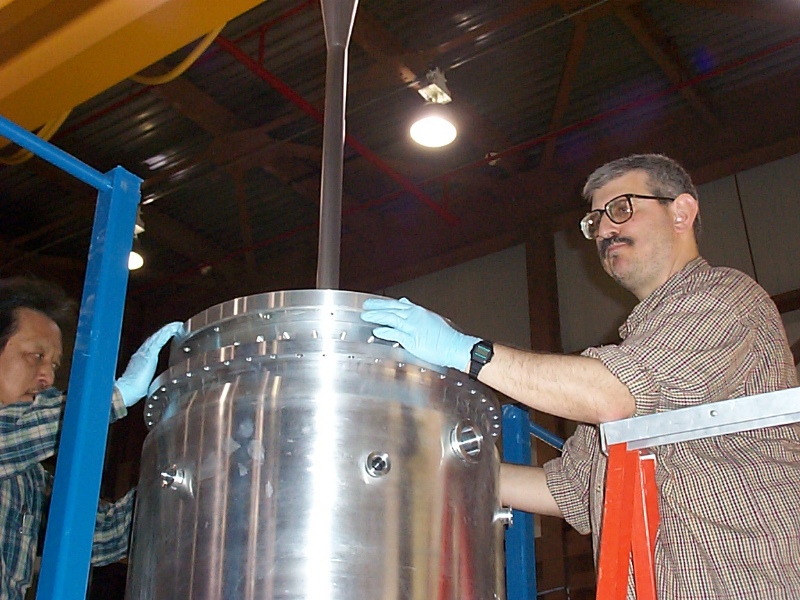
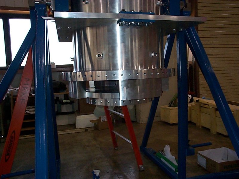
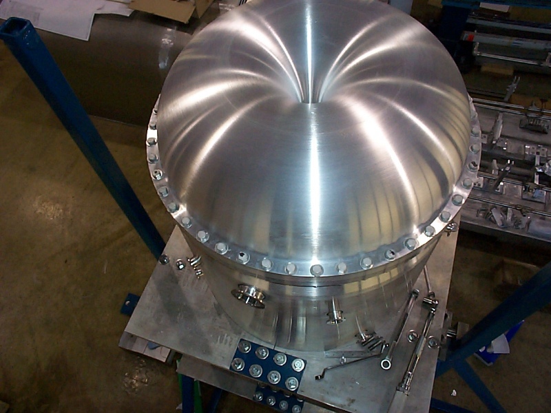
Getting the OC ready for the IC
The first picture shows the OC cleaned and ready for the next step. The second picture shows the important step of checking the verticality of the OC with an impromptu plumb bob (a nut which is hard to see on the end of a string.) We had to shim the base plates of the rotating fixture to rotate the OC into a more vertical position so that the IC wouldn't scrape as it went through. The last picture is the proof that we did indeed install the current-carrying water seal on the OC before we lowered the IC and bolted it on.
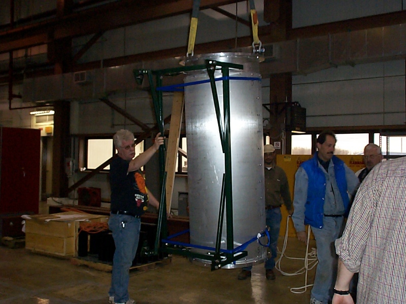
Unwrapping the IC from its cocoon
Having done its job of protecting the IC from bending during transport and rotation to vertical, all but one piece of it is stripped away. Only the downstream flange of the welding fixture remains to be used as a lifting fixture for insertion of the IC into the OC.
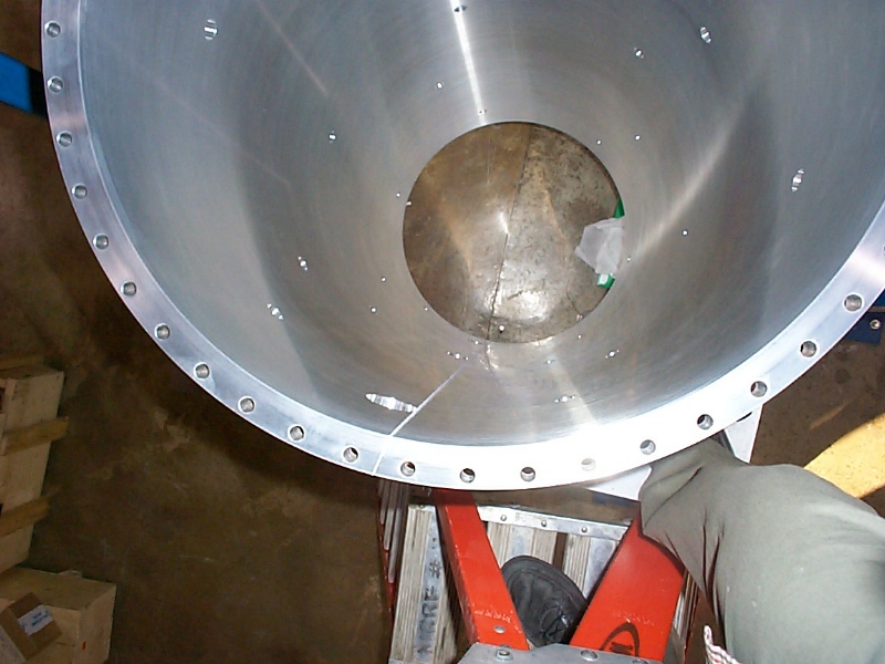
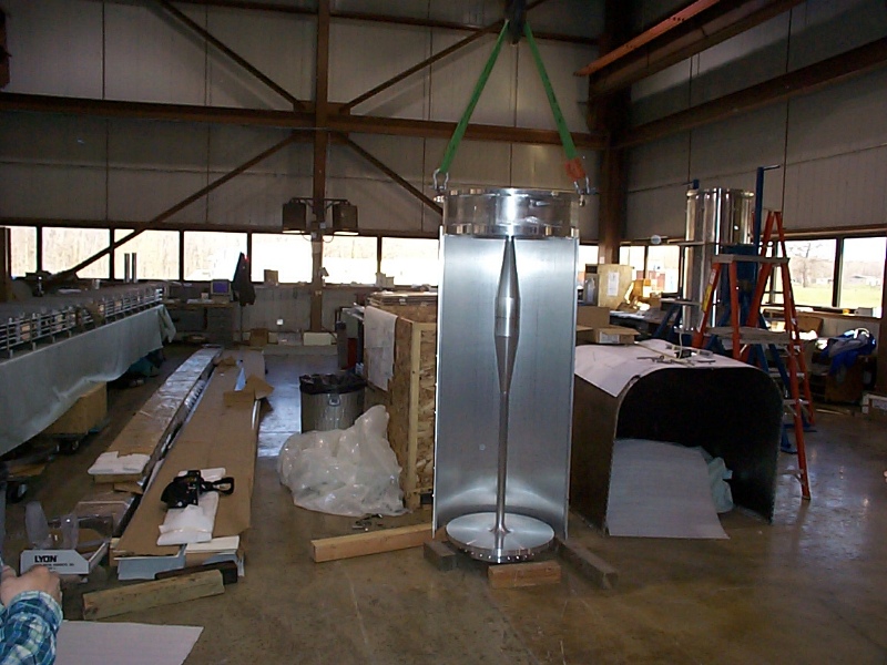
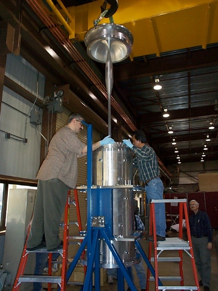
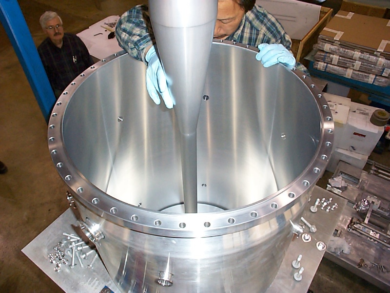
The flight of the Inner Conductor
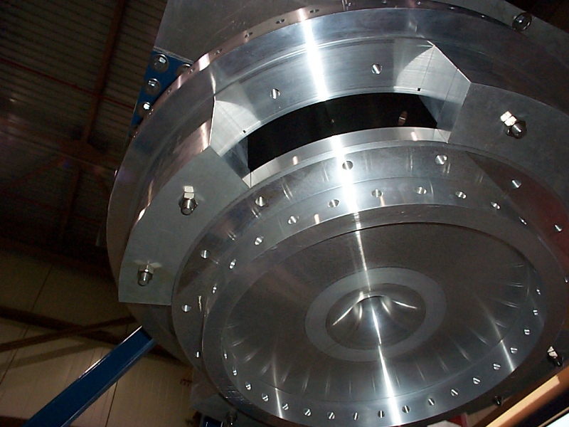
This is where the Friday the 13th phenomena got us. The first picture shows that a 4 foot sling must be used (not the 6 foot one shown) to lift the IC because the crane is at its height limit and there is still a bit to go to get the IC into the OC. Changing slings on the IC requires putting it back in the clam shells to hold it up while the slings are exchanged. Then after the fire alarm went off and the building filled with a foul smell, we learned that you can't operate the crane at MI-8 at slow speed for extended periods without stopping to let it cool off. The crane repair people told us later that day that there had been no damage to the controls or wiring of the crane, we had simply burned the accumulation of dead flies that filled the control enclosure. (As the smell dissipated it began to smell like incense.) Because the crane was out of commission for about a half hour from the thermal trip, we lowered the IC the last millimeter onto the OC by loosening the eyebolts that connected the welding fixture flange to the sling. (In case you were wondering, the bottom left picture was taken from the floor looking up through the open bottom end of the outer conductor.)
Bracket assembly to protect the IC from side-sway
These brackets protect the inner conductor from bending during rotation of the horn on the rotating fixture. There are several reasons for building rotation into the rotating fixture. First, it allows us to install the inner conductor in the only orientation that works for that operation and then flip the horn end over end and install the ceramic ring from above instead of the trickier method of jacking it up from underneath the horn. Second, the inner conductor is fairly flexible axially because of the thin downstream end cap. We need to make a height measurement between the OC and IC to make a final cut on the upstream flange that takes into account the weld shrinkage of the IC. (It is not the length it was designed to be because of weld shrinkage--about 1.5 mm shorter than it was before welding.) Making this measurement with the downstream end cap both up and down allows the static deflection of the IC to be averaged out in the final length determination. The IC would be damaged if the heavy upstream end were not restrained during the rotation operation, hence these brackets.
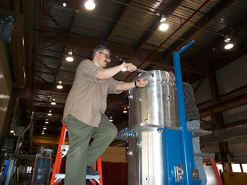
Torqueing the bolts on the downstream flange
The .375-16 bolts that connect the downstream end cap to the outer conductor must be torqued to 24 lb-ft to achieve the full crush of the seal and get the proper preload on the bolts. This torque was determined by breaking a sample of bolts and using 80% of the minimum torque required to break the bolts. This is the technique recommended by the Aluminum Association design manual. The design of the flange and the preload of the bolts should allow the bolted connection to reach the desired fatigue life. Back to the MiniBooNE Horn Main Menu Back to the Bartoszek Engineering Home Page |