Renderings of the MiniBooNE Horn Support System DesignImages on this page focus on the design of the support system that holds the horn in alignment, voltage isolates it from the horn box, and allows the horn to "breathe" during thermal and magnetic deflections. The last picture shows the support and voltage isolation components of the water system support truss. If anyone would like to see a closer view of any component, or a different rotation, just e-mail me. Same for any comments or questions. You are welcome to download any of the images. If they are used for other than private viewing, credit to Bartoszek Engineering would be appreciated.
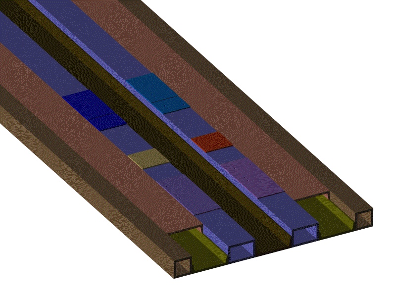
The basic design of the platform is a group of tube and c-channels welded into a skid-like structure. Pads are welded into holes cut into the tubes and the pads are machined flat with bolt holes and two grooves added after all welding. The grooves act as keys with the horn support structure to fix the location of the horn along the beam line. The pads and features must be related to features on the bottom side of the skid which mate with support structures in the target vault. Eventually the horn's position in the box is transferred by survey to targets on the upstream end of the platform that would be visible in the target hall tunnel.
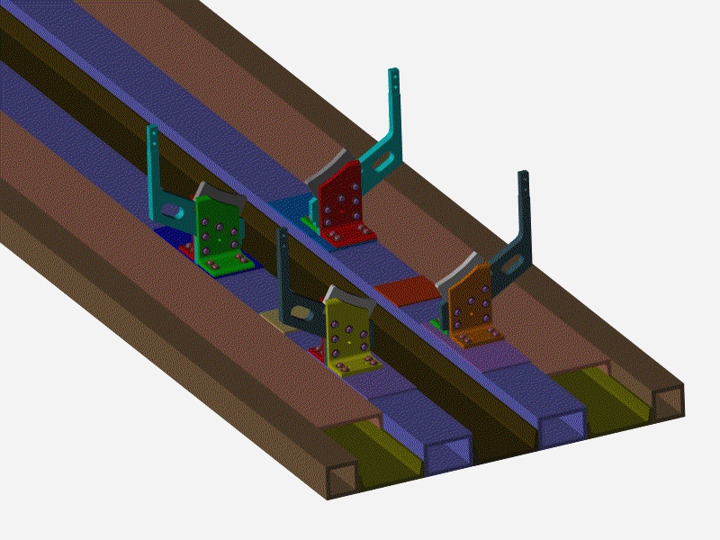
The voltage isolation of the support structure is accomplished by ceramics (shown in white and grey,) in between the aluminum angles and the outer conductor of the horn. The ceramics are mounted into pockets formed by the aluminum plates and angles. See the next picture for how the outer conductor has a matching keyway that the upstream ceramic engages with. The ceramic transmits any axial forces into the aluminum angle structure, which transmits these loads into the keyway in the platform pad.
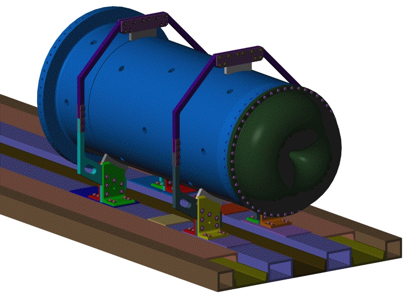
In this view the horn is installed on its ceramics and another plate and ceramic structure is bolted around the top of the horn to prevent it from being lifted off the lower ceramics, especially during crane handling operations. You can see the notch on the upstream end of the outer conductor that locks its position along the beam line onto the platform.
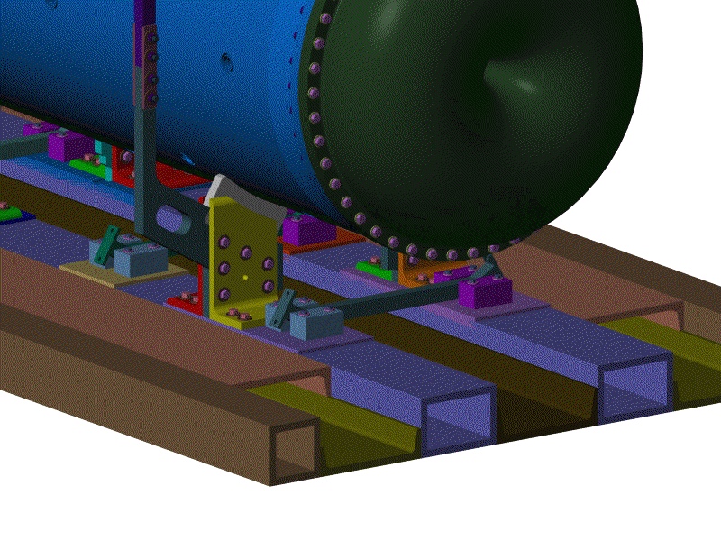
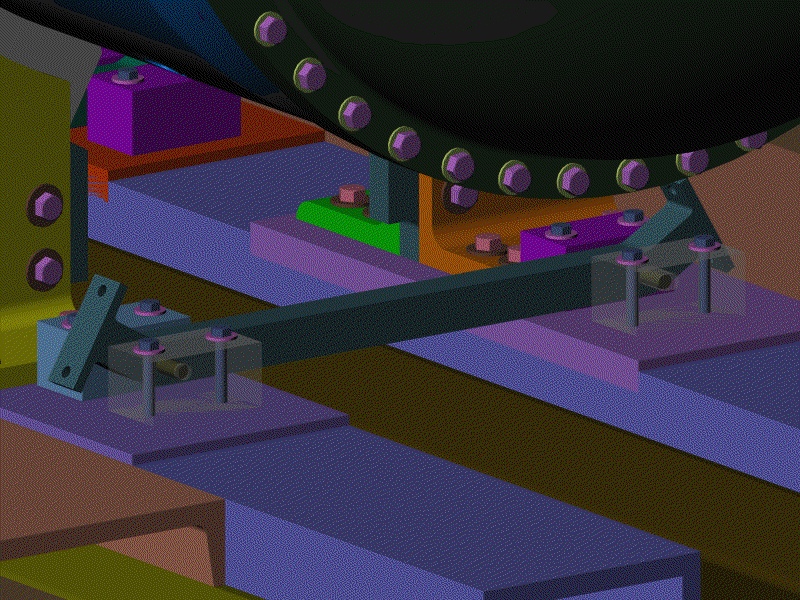
The light blue and purple blocks shown bolted down to the machined pads on the platform are made of ceramic. They voltage isolate the truss that supports the water system from the base platform. See the next picture for details of the hole and slot features in these blocks.
The ceramic blocks on the right side of the platform (facing downstream) have holes that engage machined dowel pins pressed into the water truss arm. The ceramic blocks on the left side have slots so that if there is any deflection of the base platform or any kind of differential thermal phenomena the truss can "breathe" with respect to the platform.
Back to the Horn Renderings Main Menu
Back to the MiniBooNE Horn Main Menu
Back to the Bartoszek Engineering Home Page
|