|
The T2K Horn 2 Fixturing at CU
This page shows some of the tooling we built to aid in assembly of horn 2 at Boulder. The positional tolerances of the horn with respect to its frame were fairly tight. The horn has two different water systems, one to cool the horn and the other to cool the support frame. The horn cooling system has pipes to bring the water down to the horn spray nozzles, and a suction system to bring the water out of the horn water reservoir and return it to the filtering system. It receives electrical current through the striplines. It has a pipe to vent hydrogen gas out of the horn. All of these pipes and striplines have remotely operated quick disconnect couplings at the top of the support frame which have to be positioned accurately to mate with the pipe connections in the module that the horn frame hangs from. The tooling plate grouted to the floor creates an accurate level reference system to begin the assembly.
Click on any of the thumbnails to get an enlarged view. You are welcome to download any of the images. If they are used for other than private viewing, credit to the T2K collaboration and Bartoszek Engineering would be appreciated.
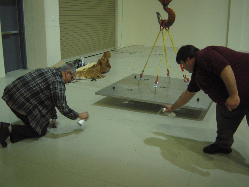
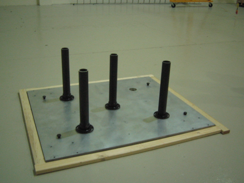
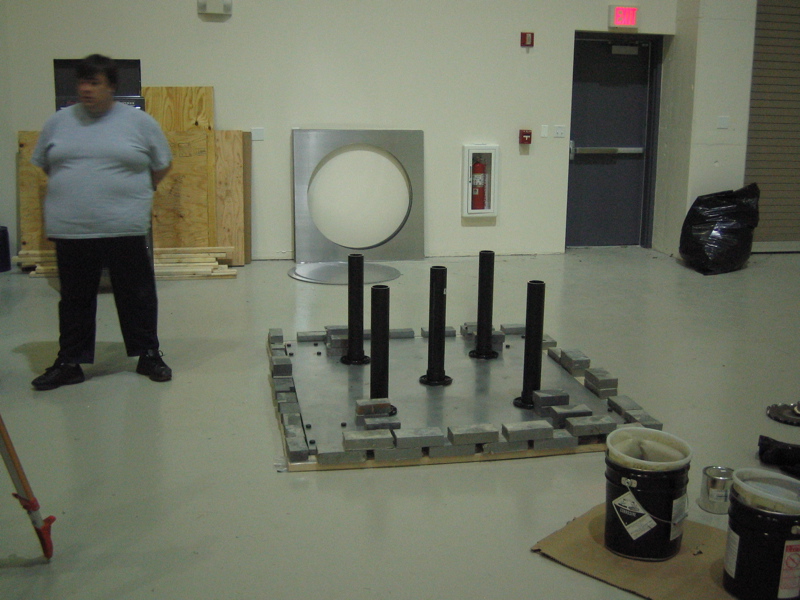
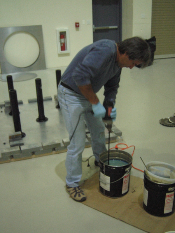
These first three pictures show us preparing the floor with mold release and laying the plate down. The plate is then fitted out with a dam all the way around to prevent the grout from escaping. The black tubes are for pouring the grout in and allowing it to build up head so that it forces itself all the way under the plate.
We used a two part epoxy grout from Unisorb to grout under the plate. This grout has about a half hour working life before it cures and is very exothermic. It also does not shrink, so forms a very stable base under a machine plate. After scraping off the excess grout from the top of the plate, the surface was perfect as an assembly base.
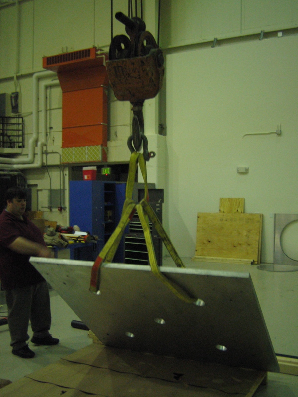
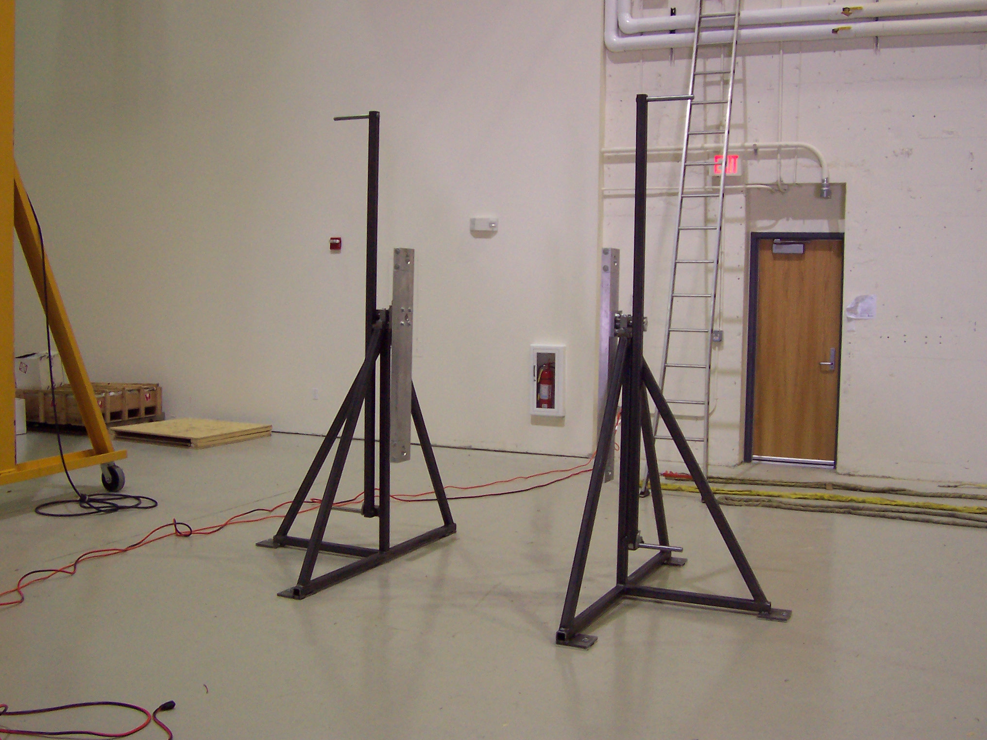
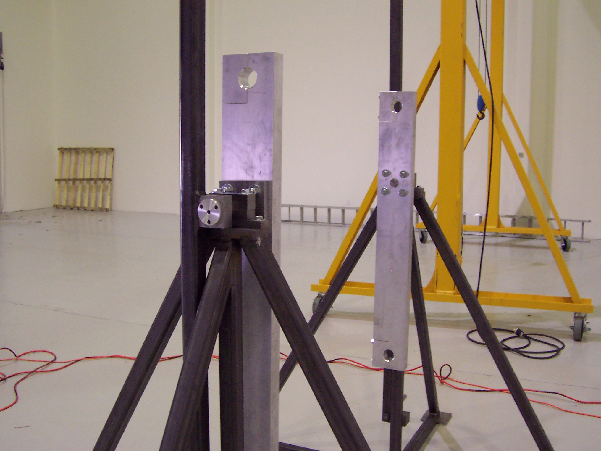
The rotating horn assembly fixture
This fixture is absolutely critical in the assembly of a typical horn. It allows the inner conductor to be lowered into the outer conductor in one orientation, then it can be flipped 180 degrees to allow the ceramic ring to be carefully lowered onto the upstream end and fastened in place. It is also convenient to attach water ports in more comfortable positions. In the background of the second picture you can see the A frame gantry crane we used for precise motions of the inner conductor and ceramic ring. For large motions of boxes and crates that we received at the roll-up door, we used the 100 year old building crane in the room.
Back to the Bartoszek Engineering T2K Main Page
Back to the Bartoszek Engineering Projects Page
Back to the Bartoszek Engineering Home Page
|