|
The Assembly of Horn 2 at CU-Boulder, 06-08
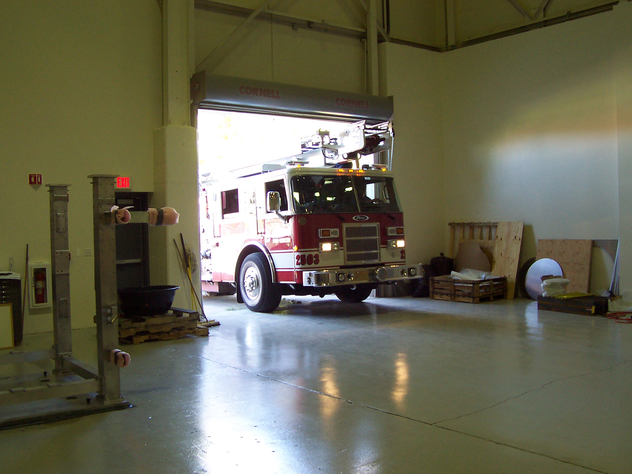
The pictures that follow show a detailed look at how horns (in this size range) get built. The work took place in a large building at CU where there used to be a small particle accelerator. The crane coverage was a 100 year old crane that broke down once (which is the reason for the pictures with fire trucks in them.) It was a very satisfying three week period where it all came together.
Click on any of the thumbnails to get an enlarged view. You are welcome to download any of the images. If they are used for other than private viewing, credit to the T2K collaboration and Bartoszek Engineering would be appreciated.
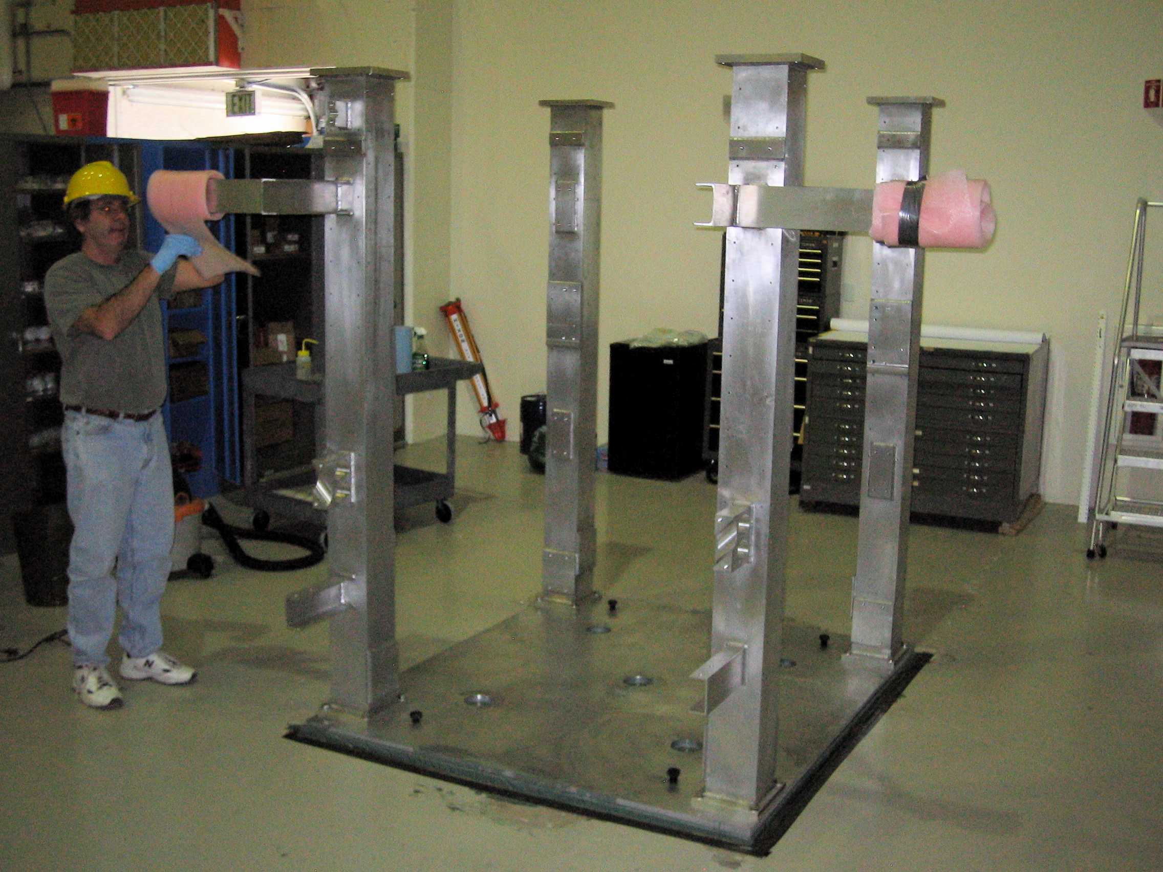
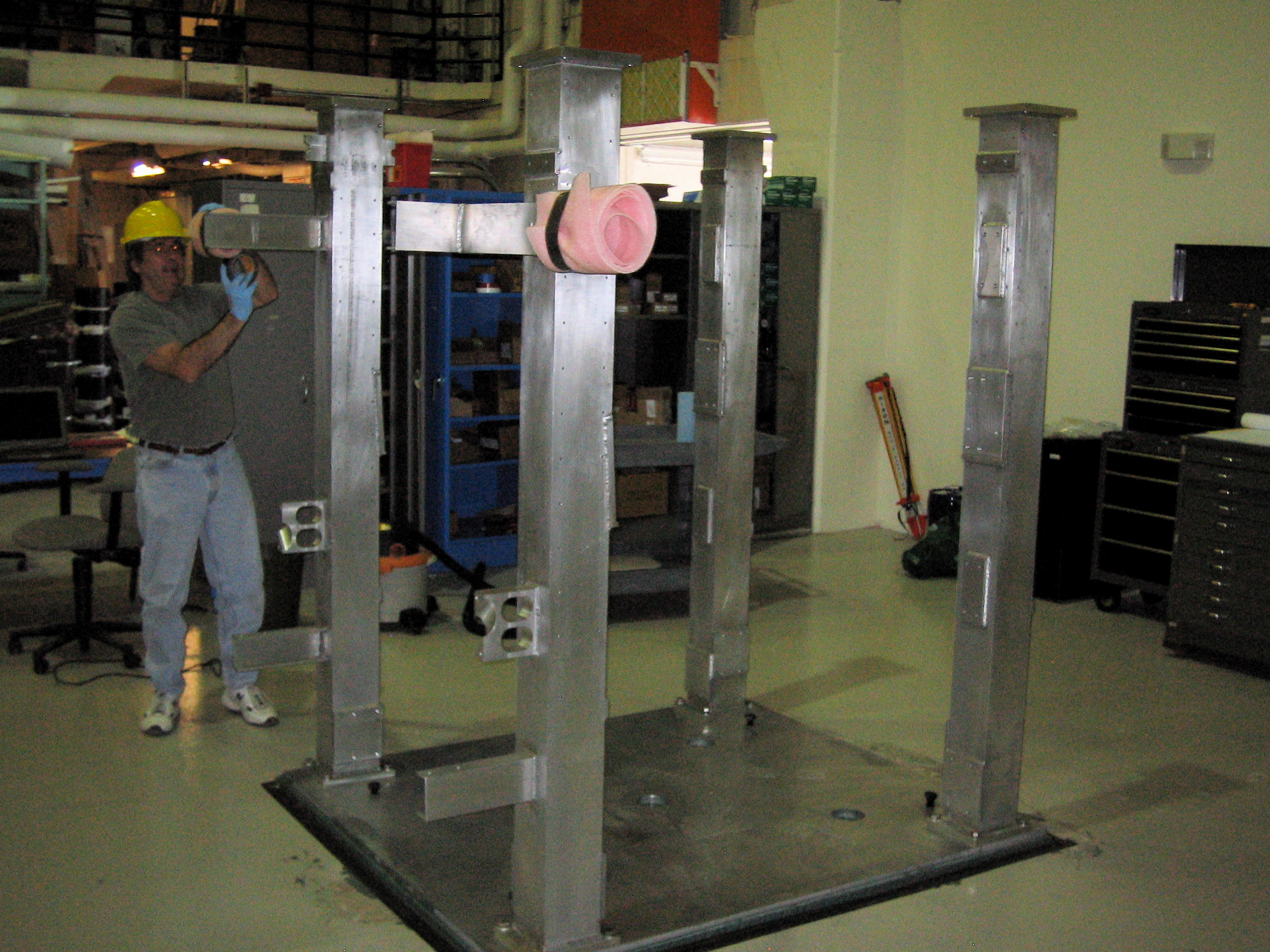
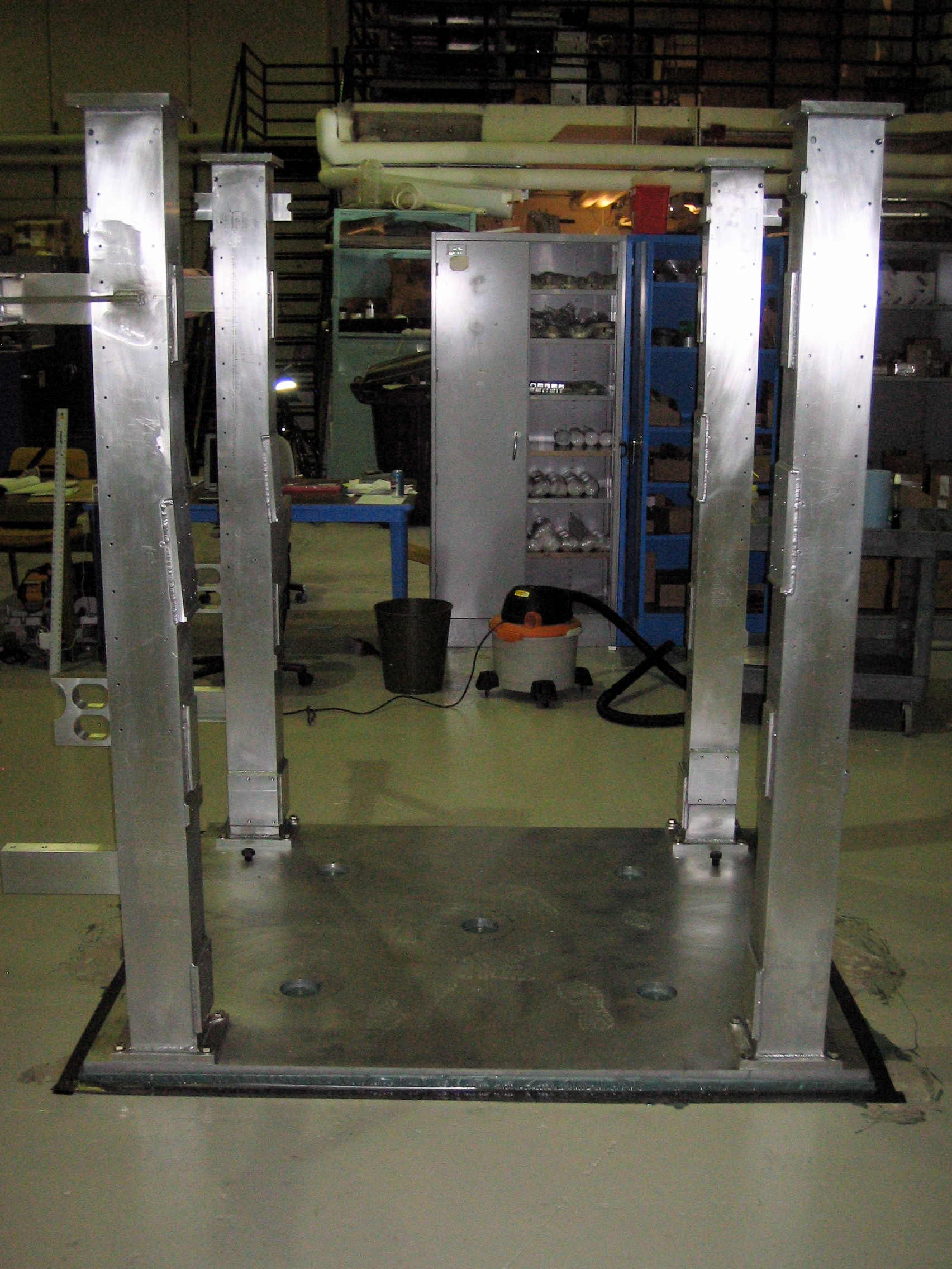
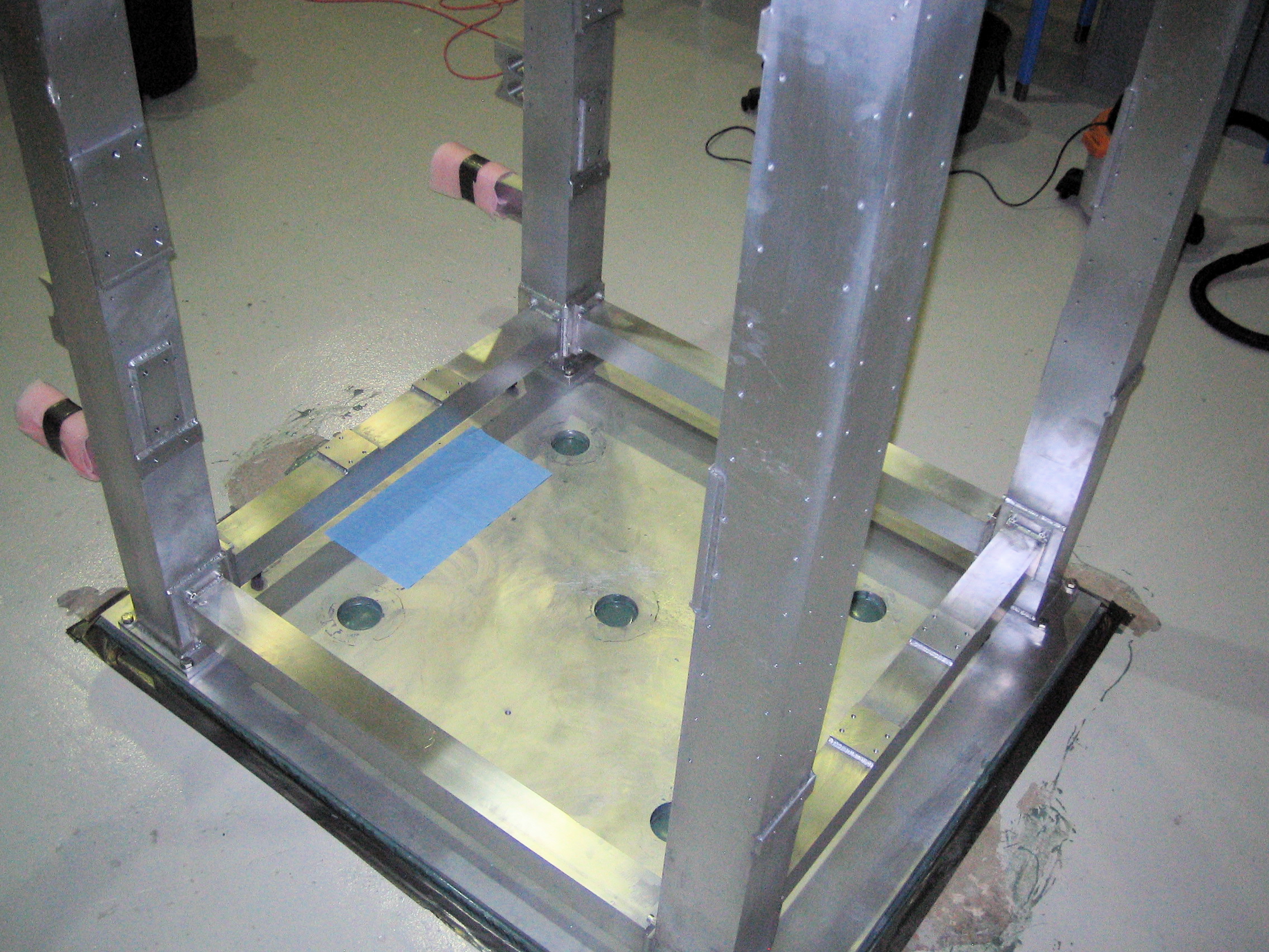
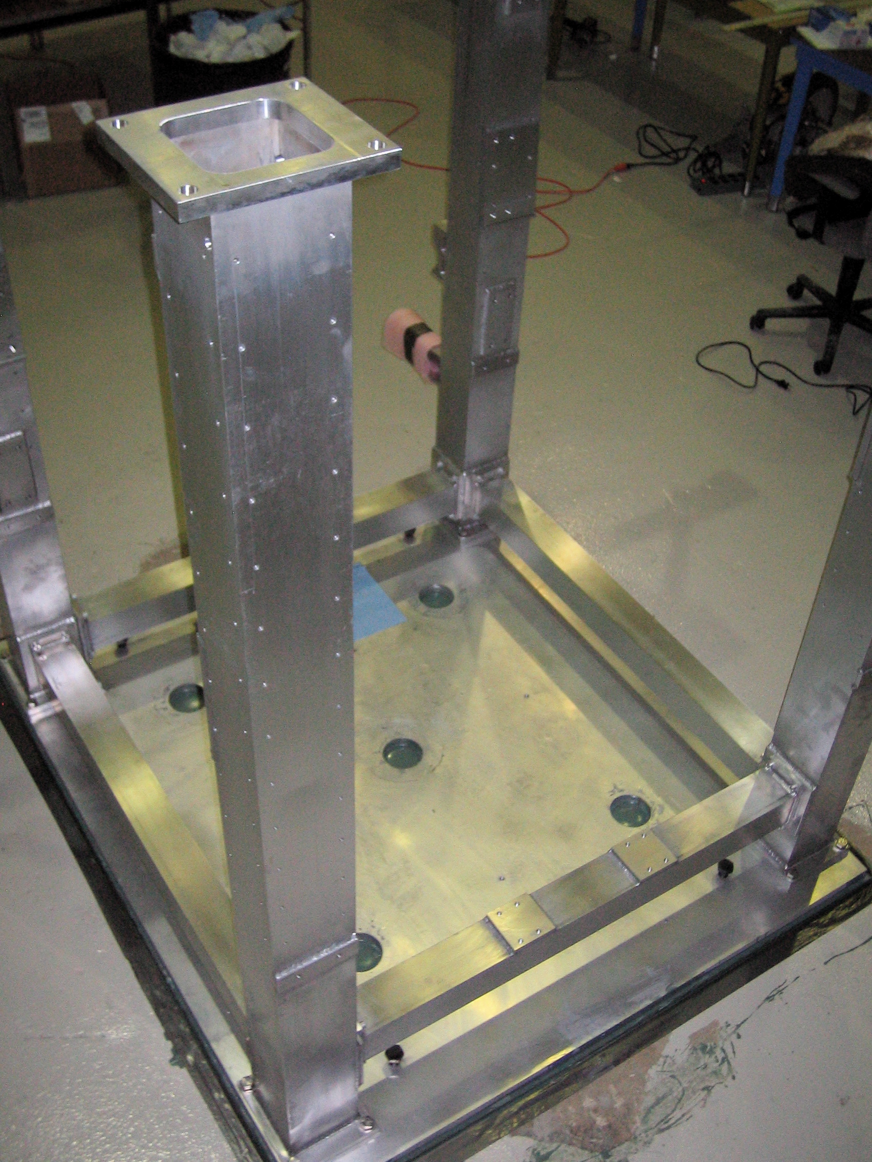
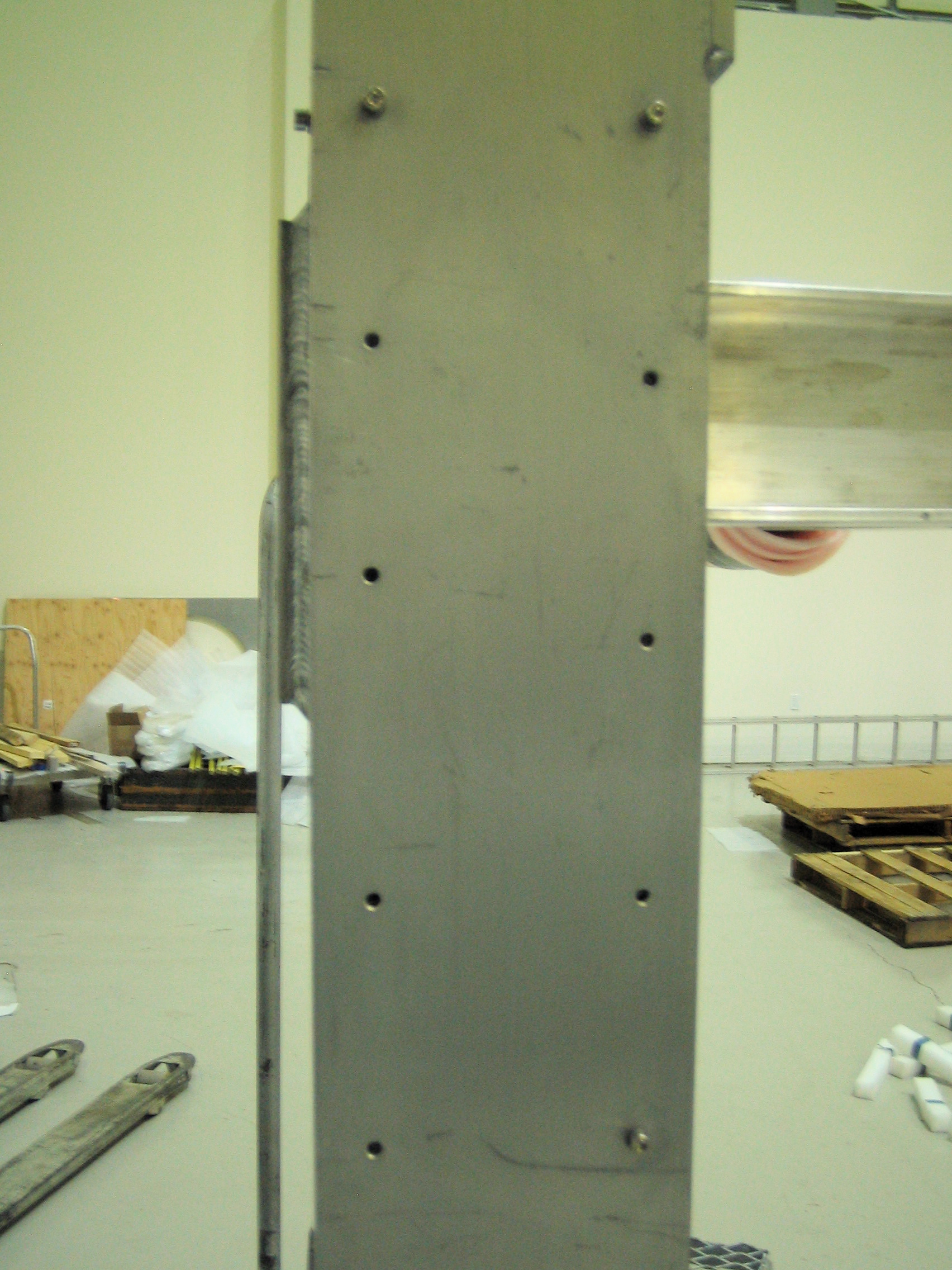
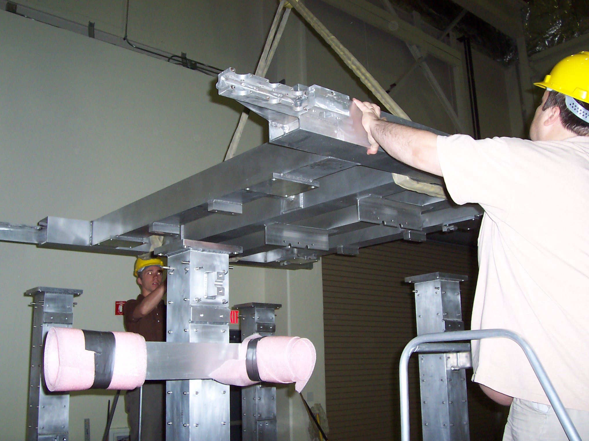
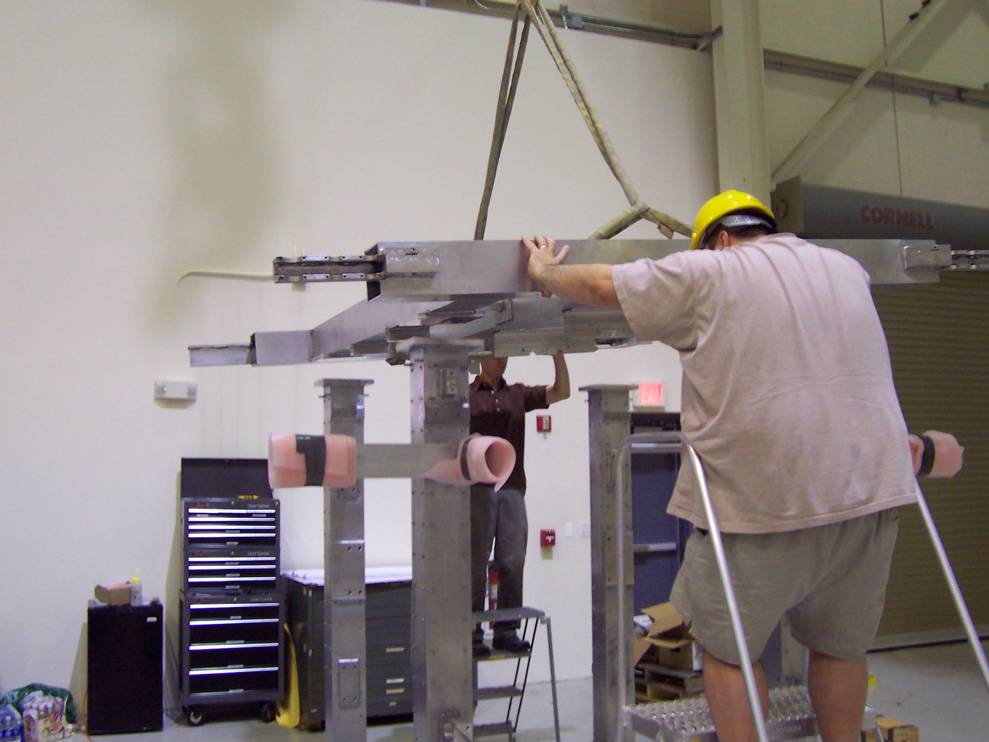
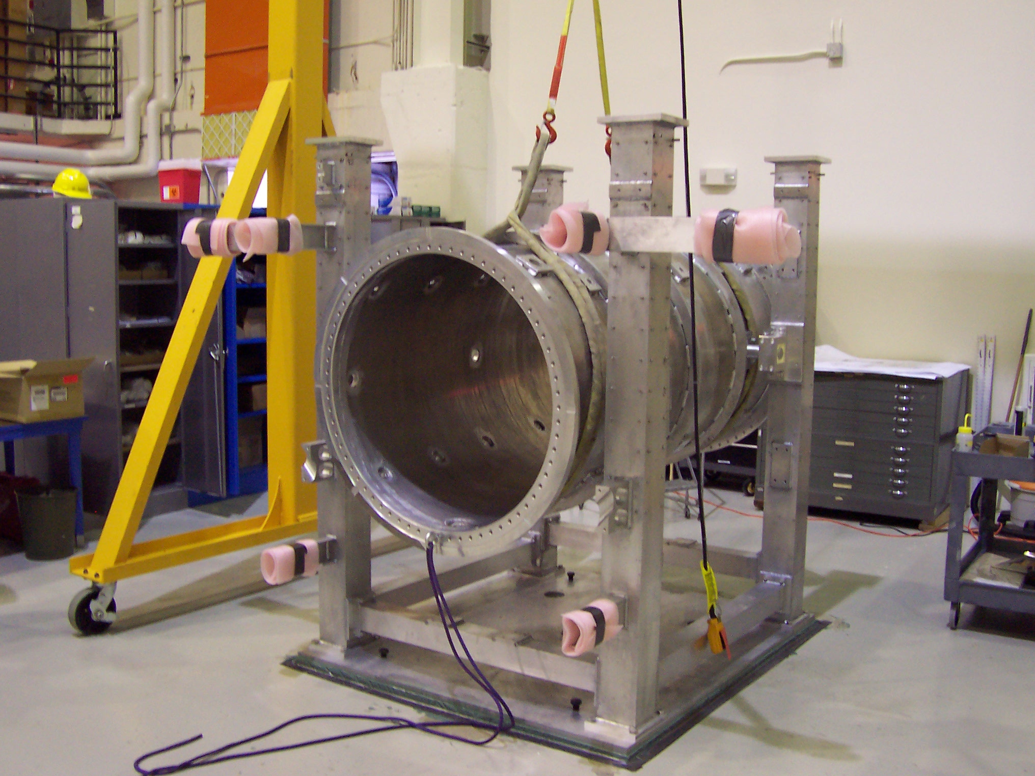
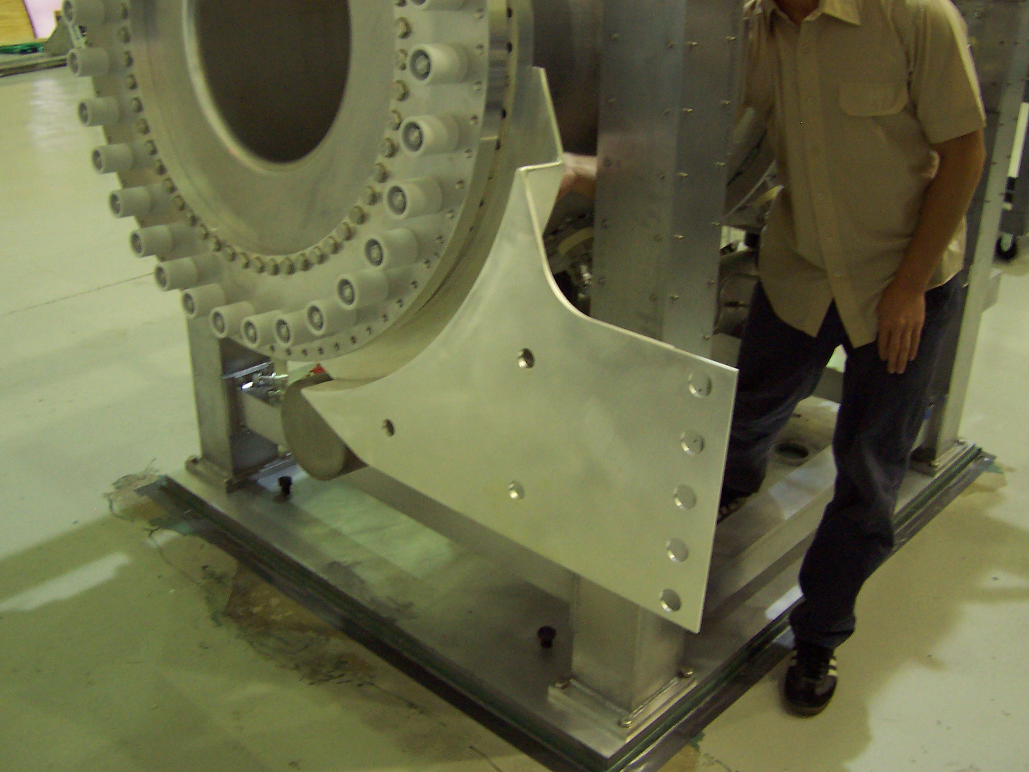
The pictures above show the mounting of the four columns that support the horn. Everything added to the structure starts with the placement of these columns. These pictures show the frame cooling tubes that are mounted inside the columns. The radiation level in the T2K target hall is high enough that the support structure will heat up at full beam power. This heat is taken away by a water cooled manifold.
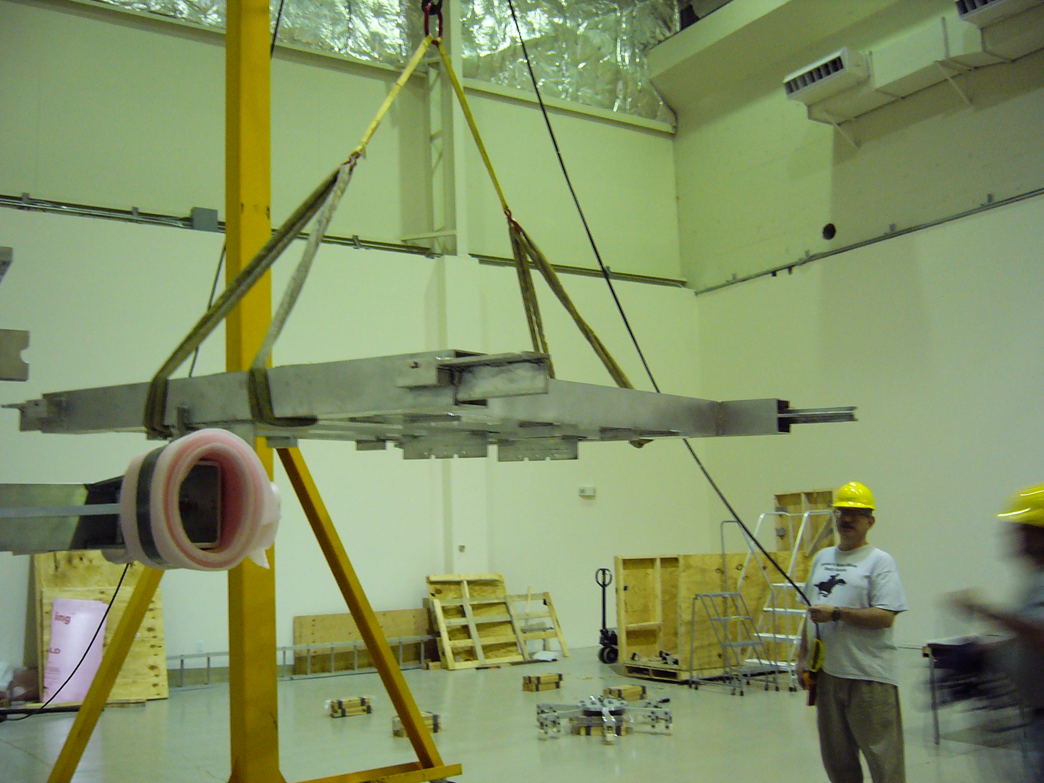
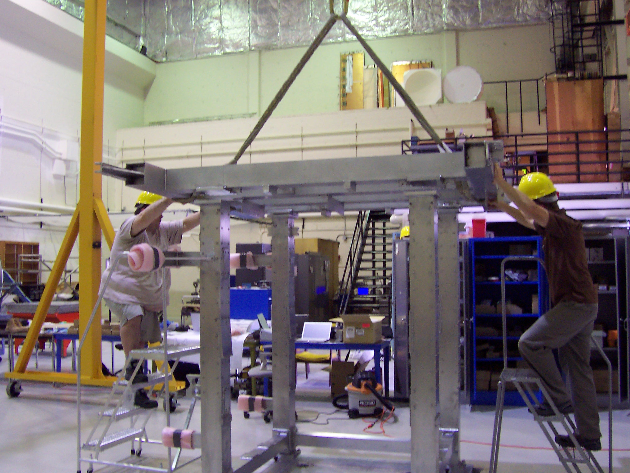
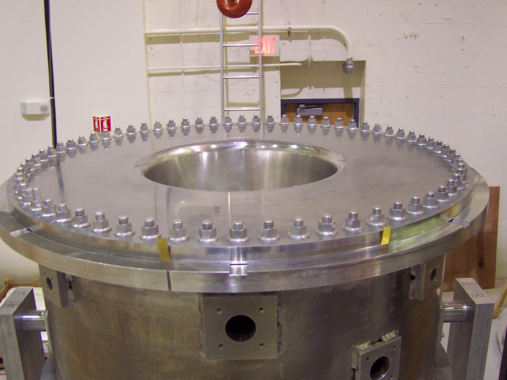
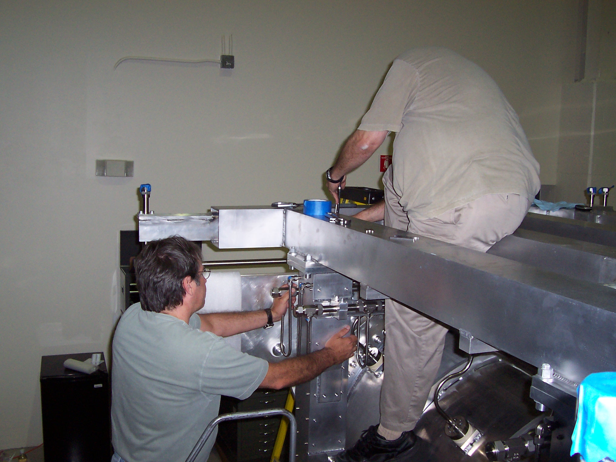
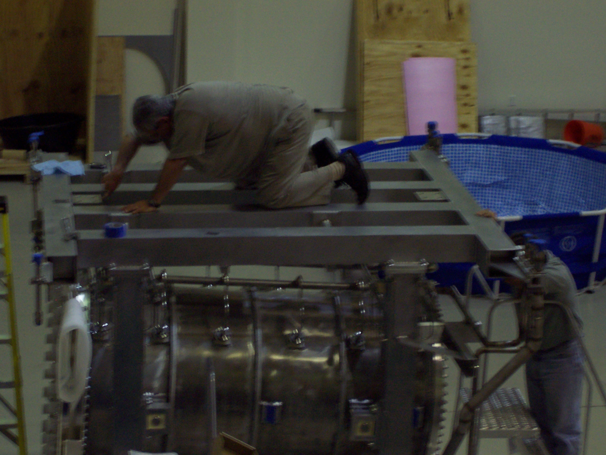
The above pictures show us test fitting the top frame to the columns to make sure everything looks right. We did very little measuring of parts prior to assembly, so test fits discovered manufacturing problems.
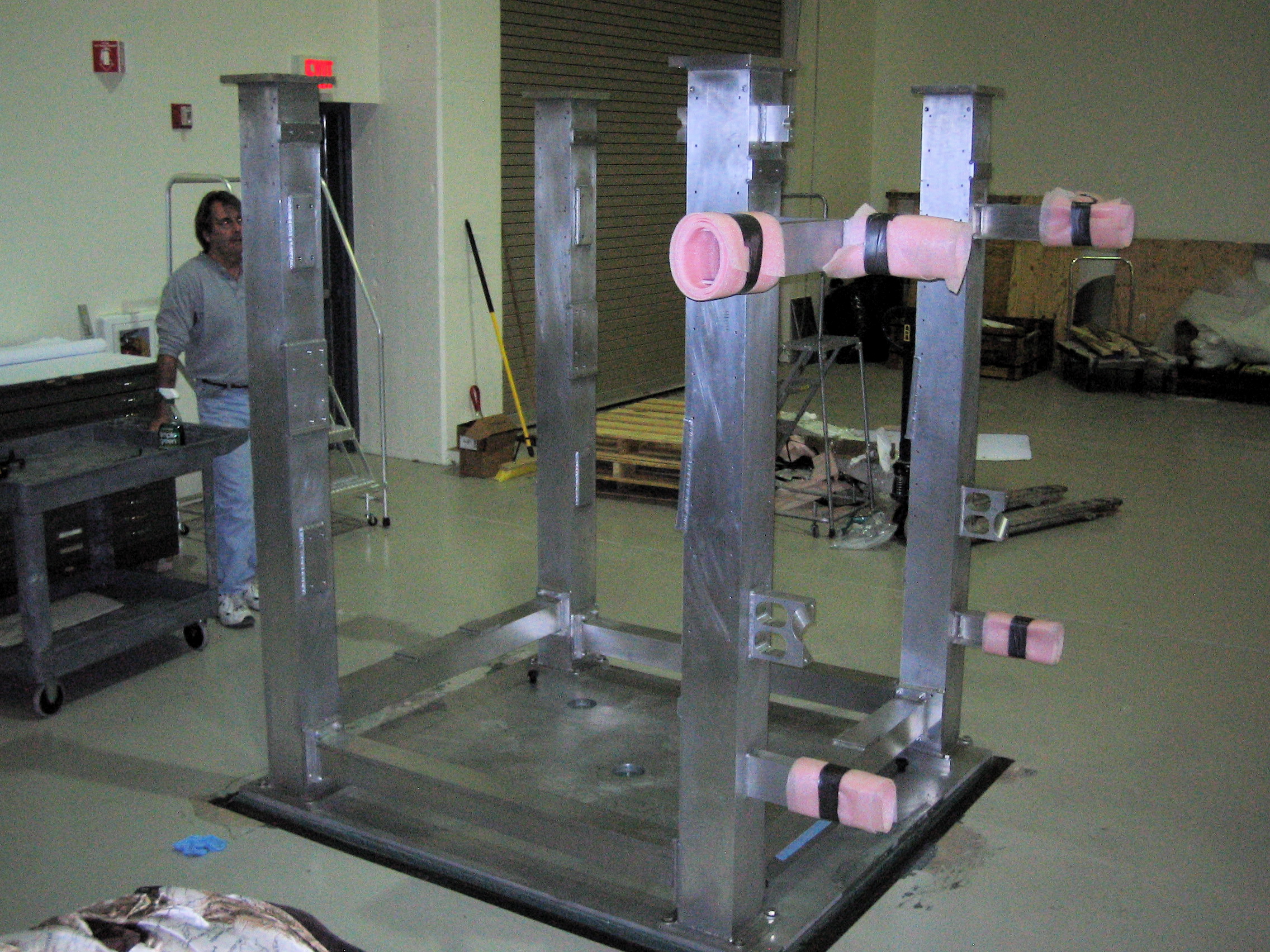
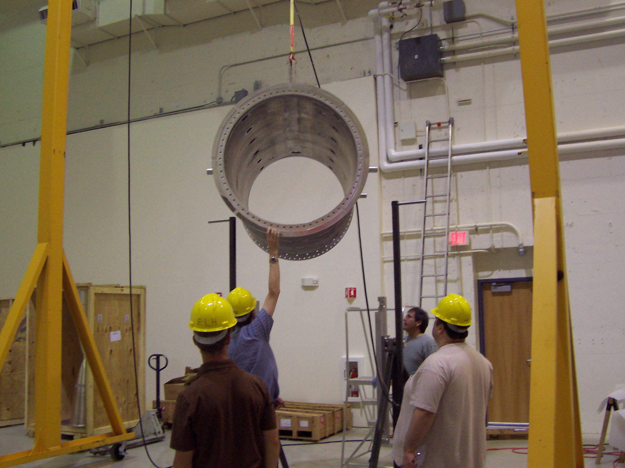
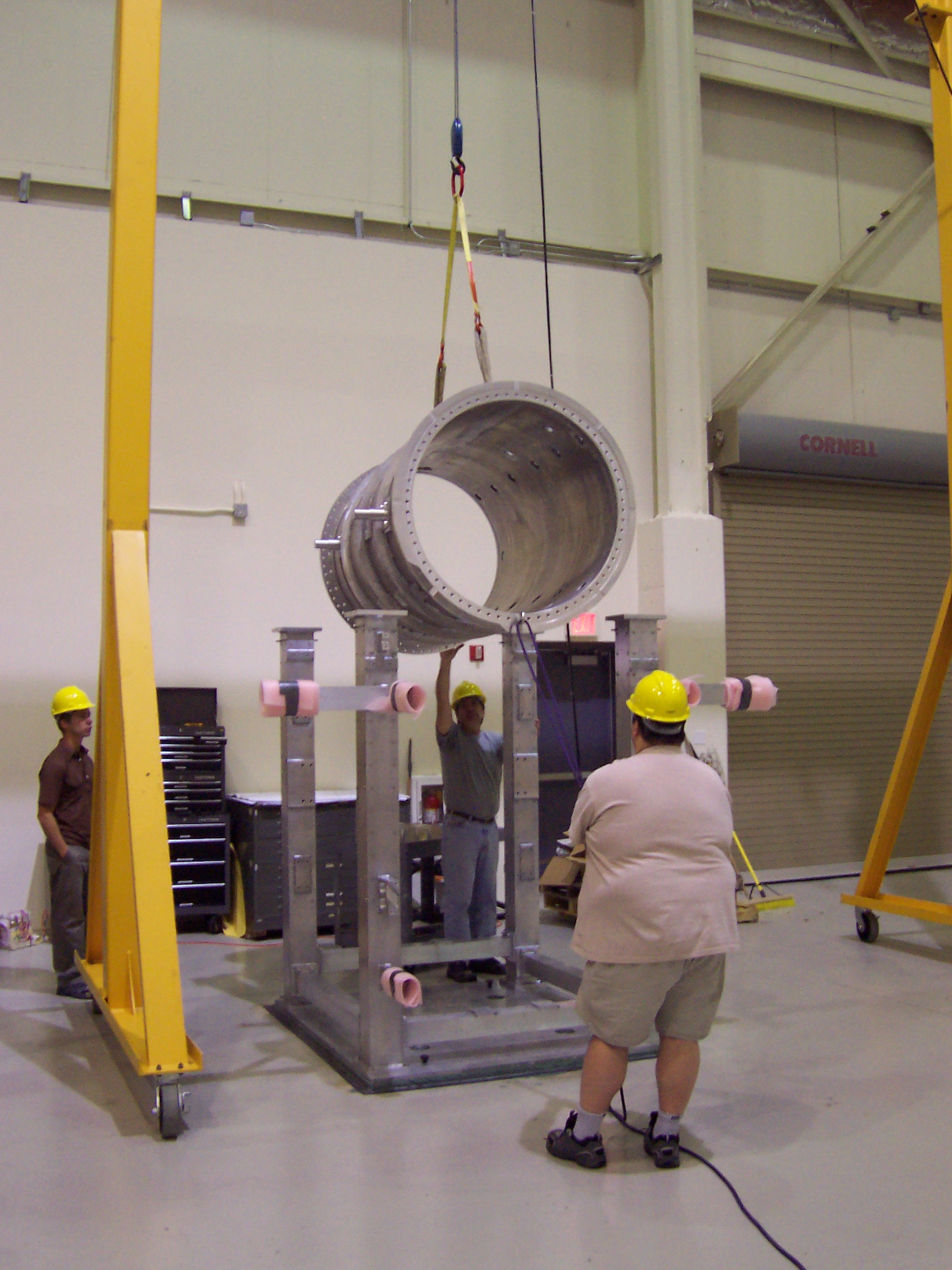
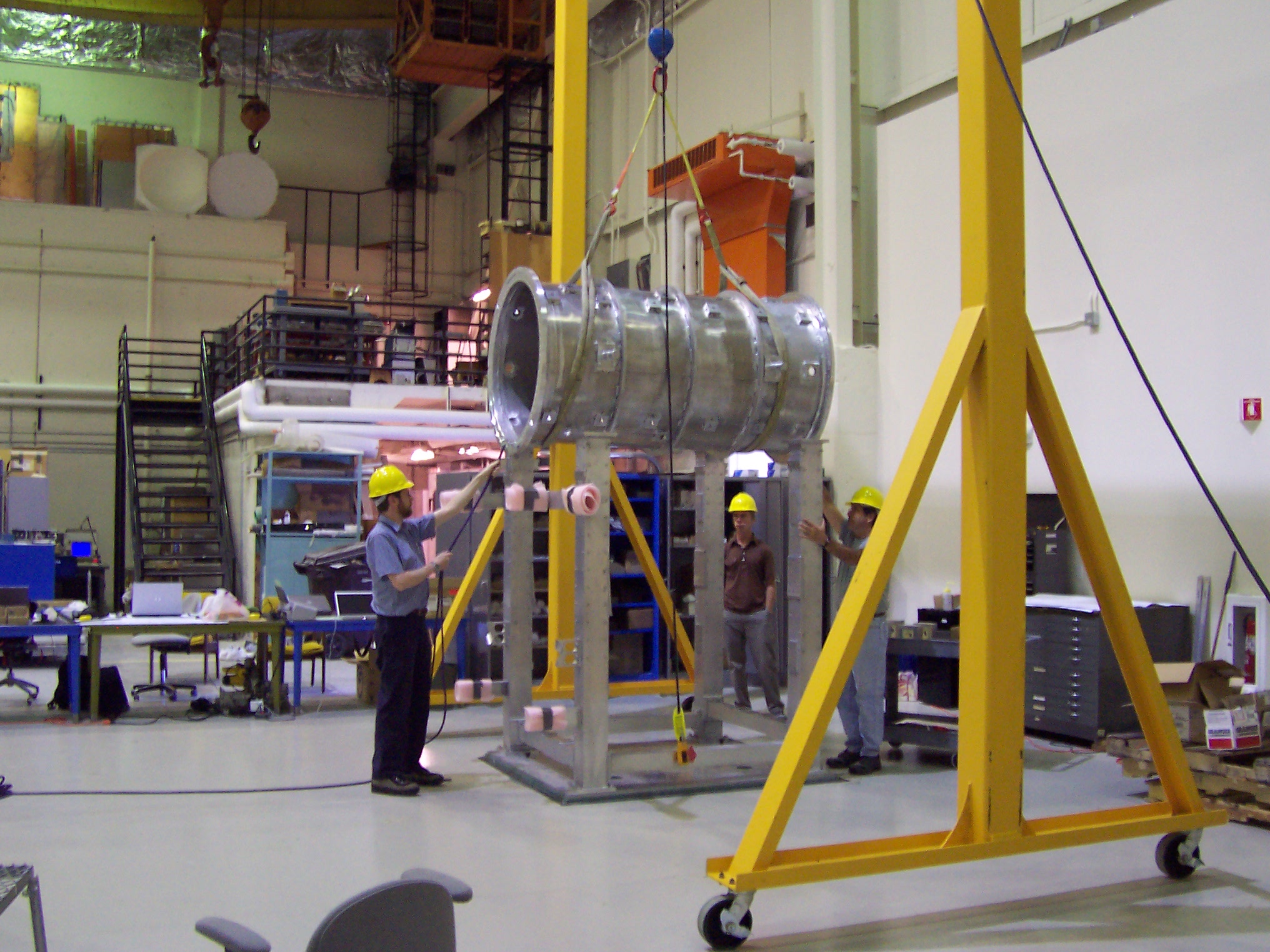
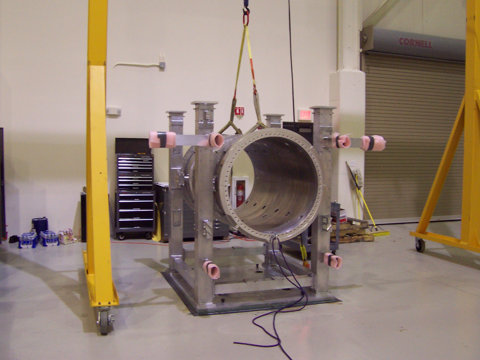
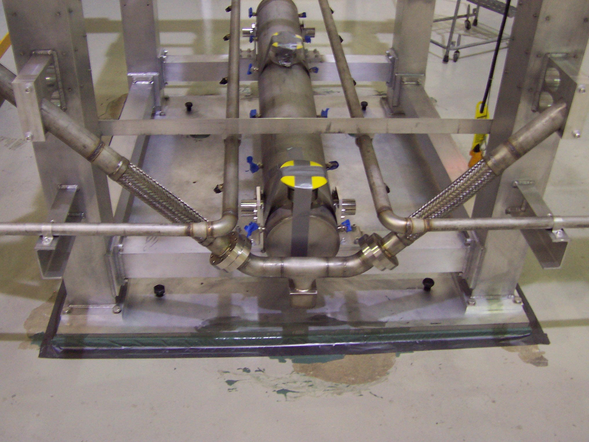
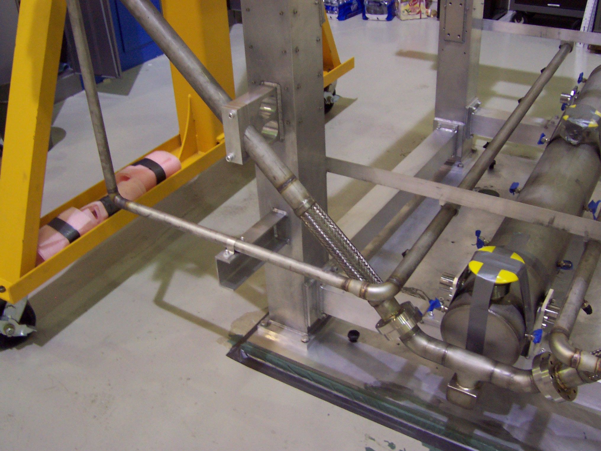
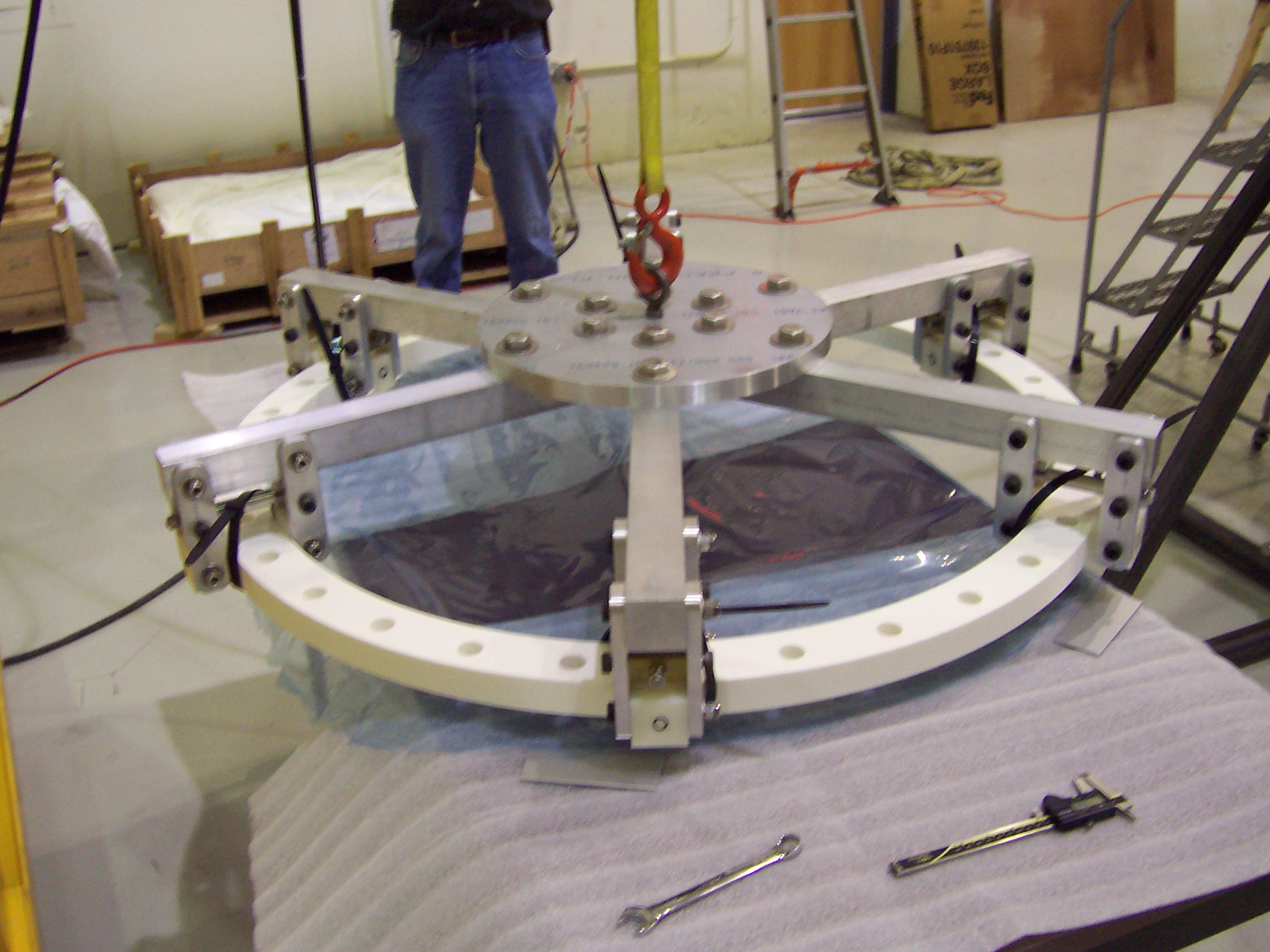
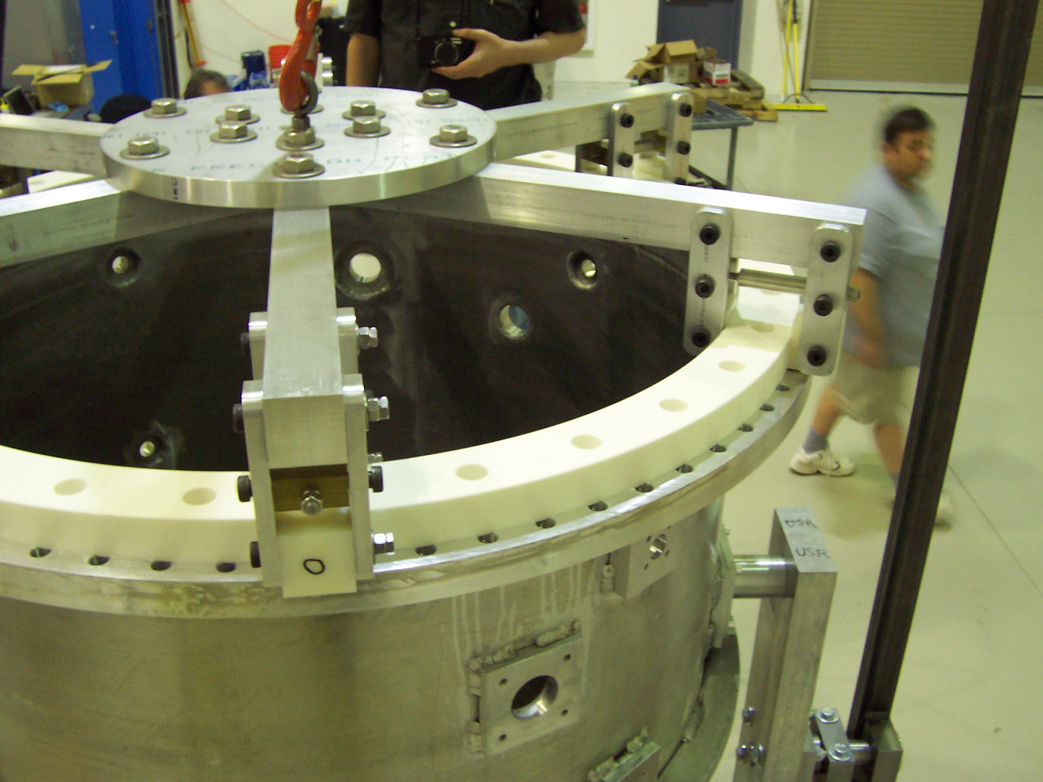
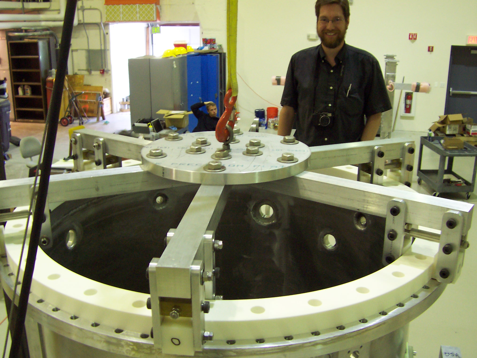
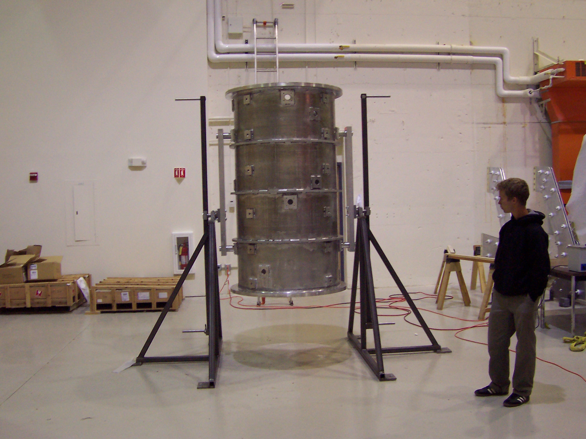
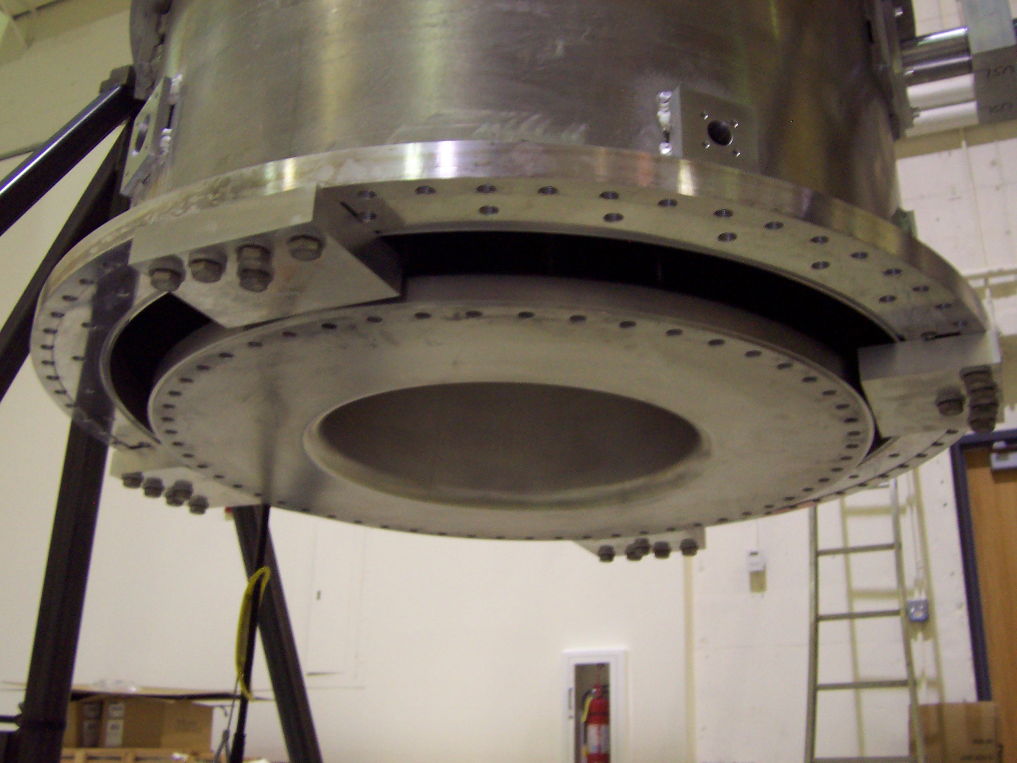
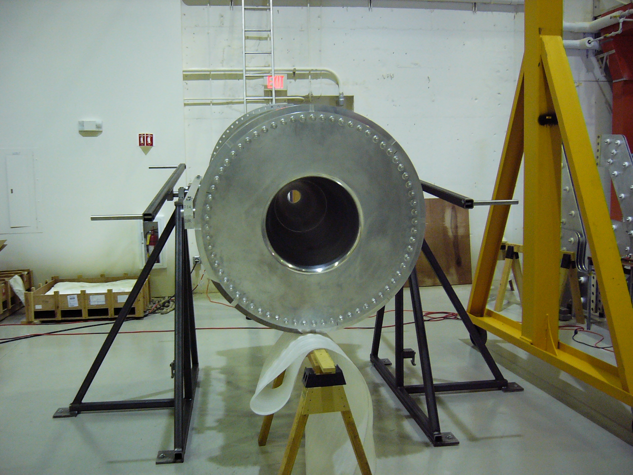
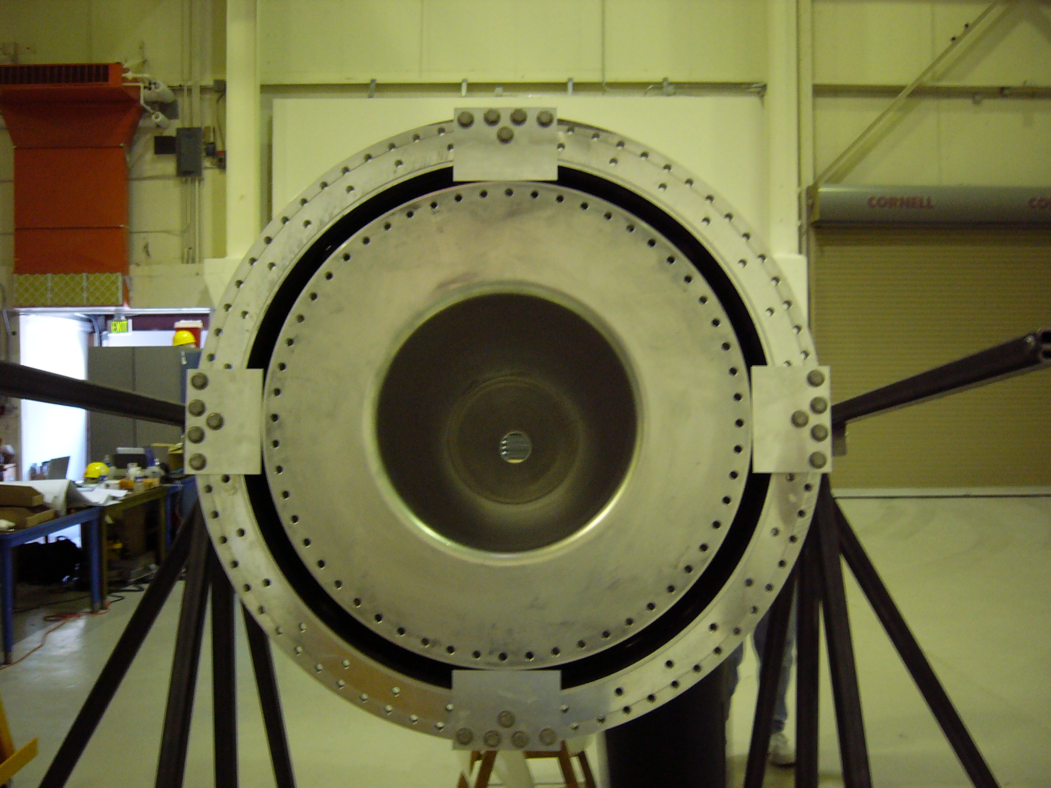
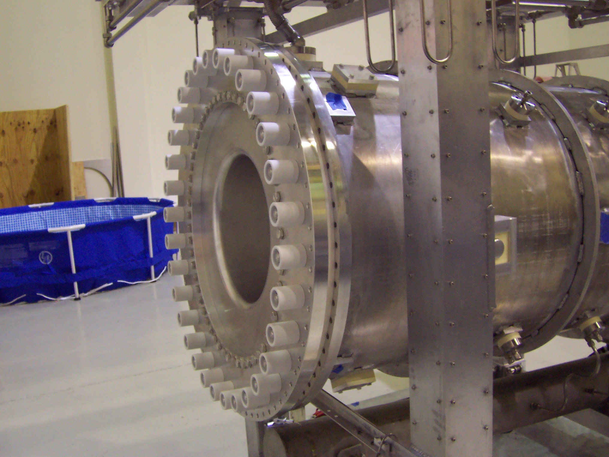
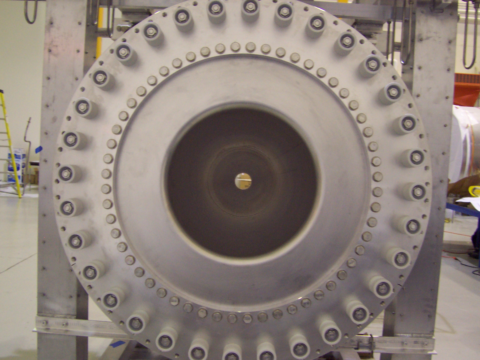
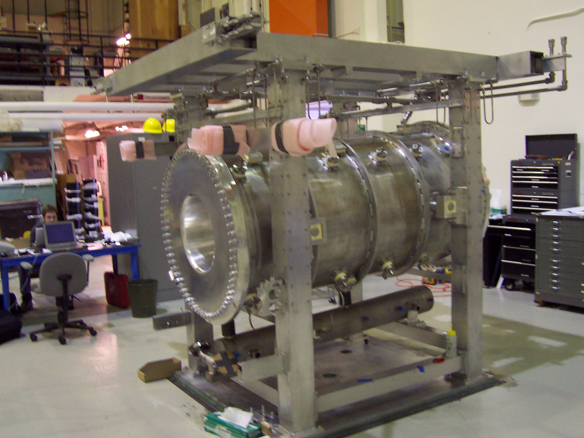
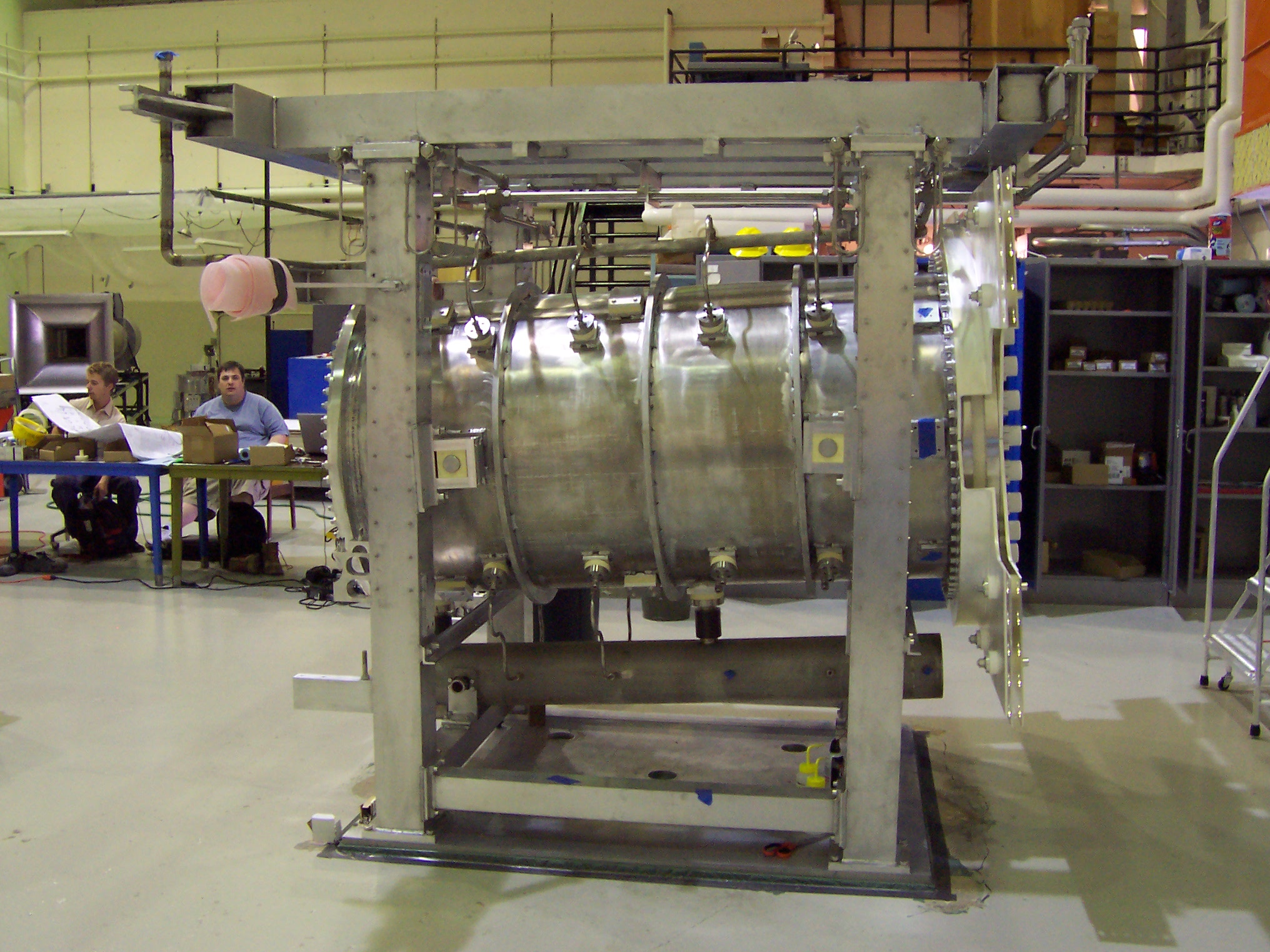
This sequence of photos shows test fitting of the outer conductor into the frame. We didn't need to do any internal horn assembly to make this check, so that's why there is no inner conductor in the horn. The above pictures show the mounting of the drain tank that collects cooling water from the horn and allows it to be pumped back the RAW (Radioactive Water) system for filtering and deionizing.
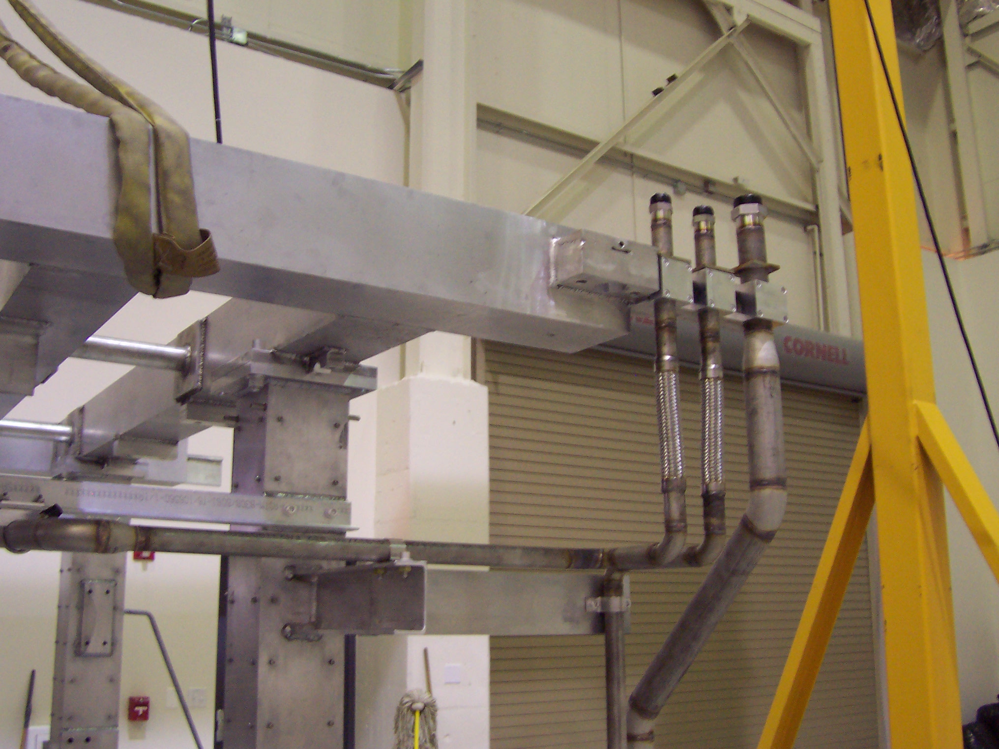
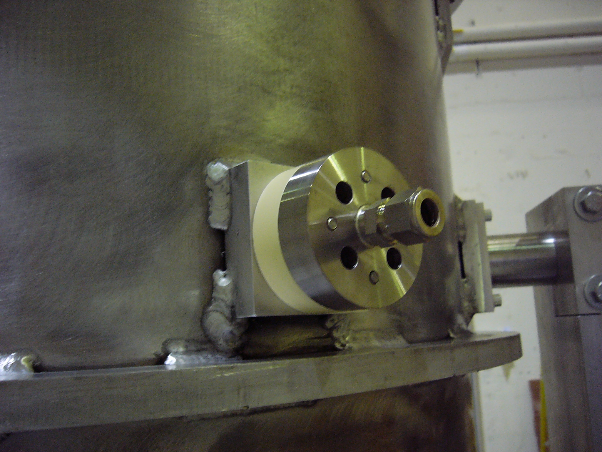
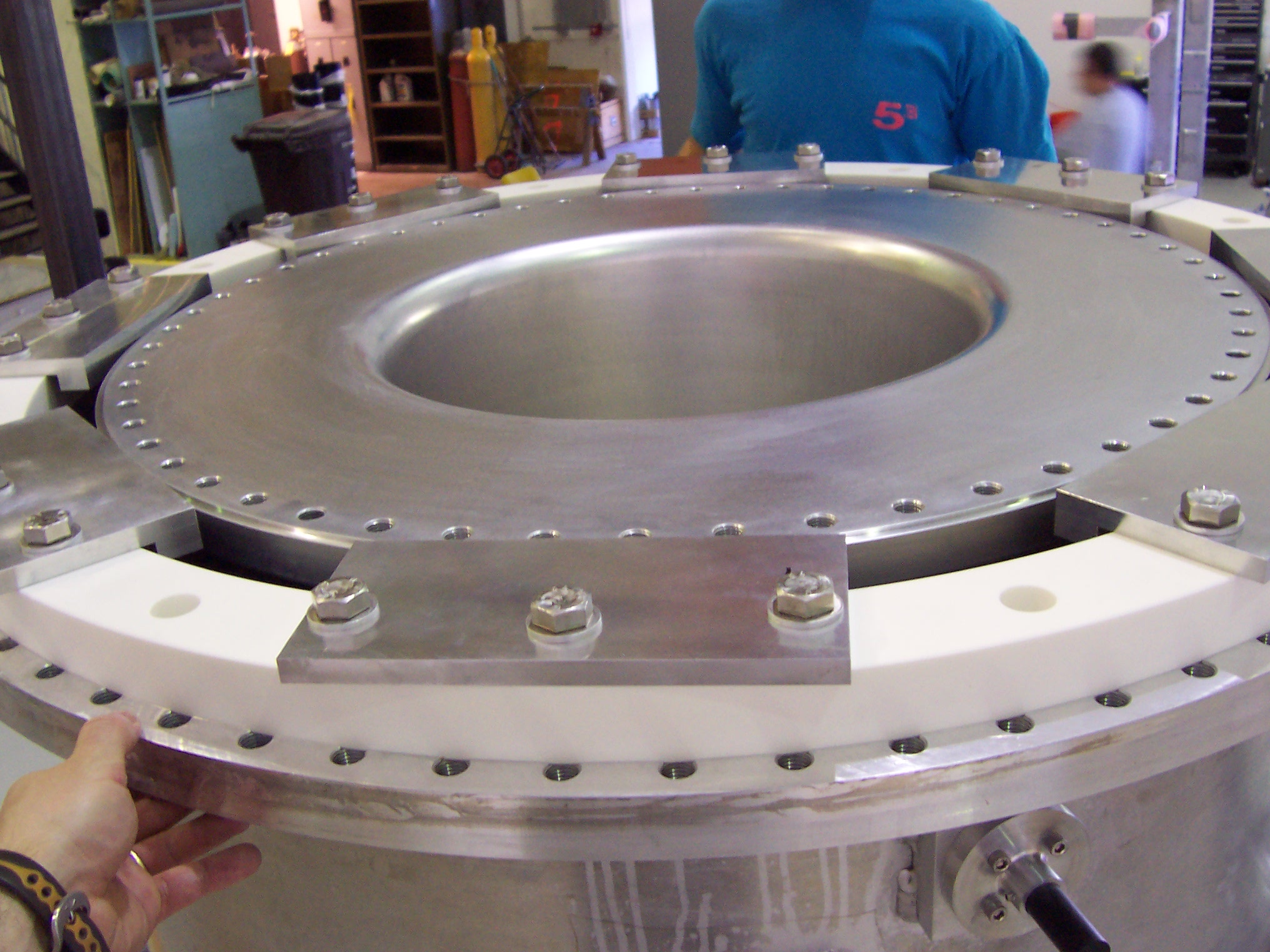
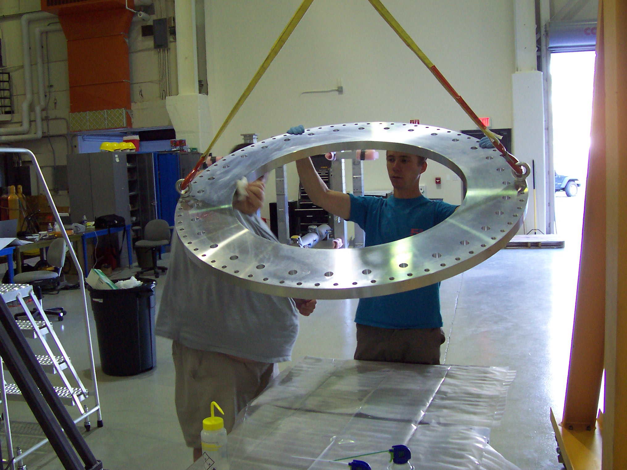
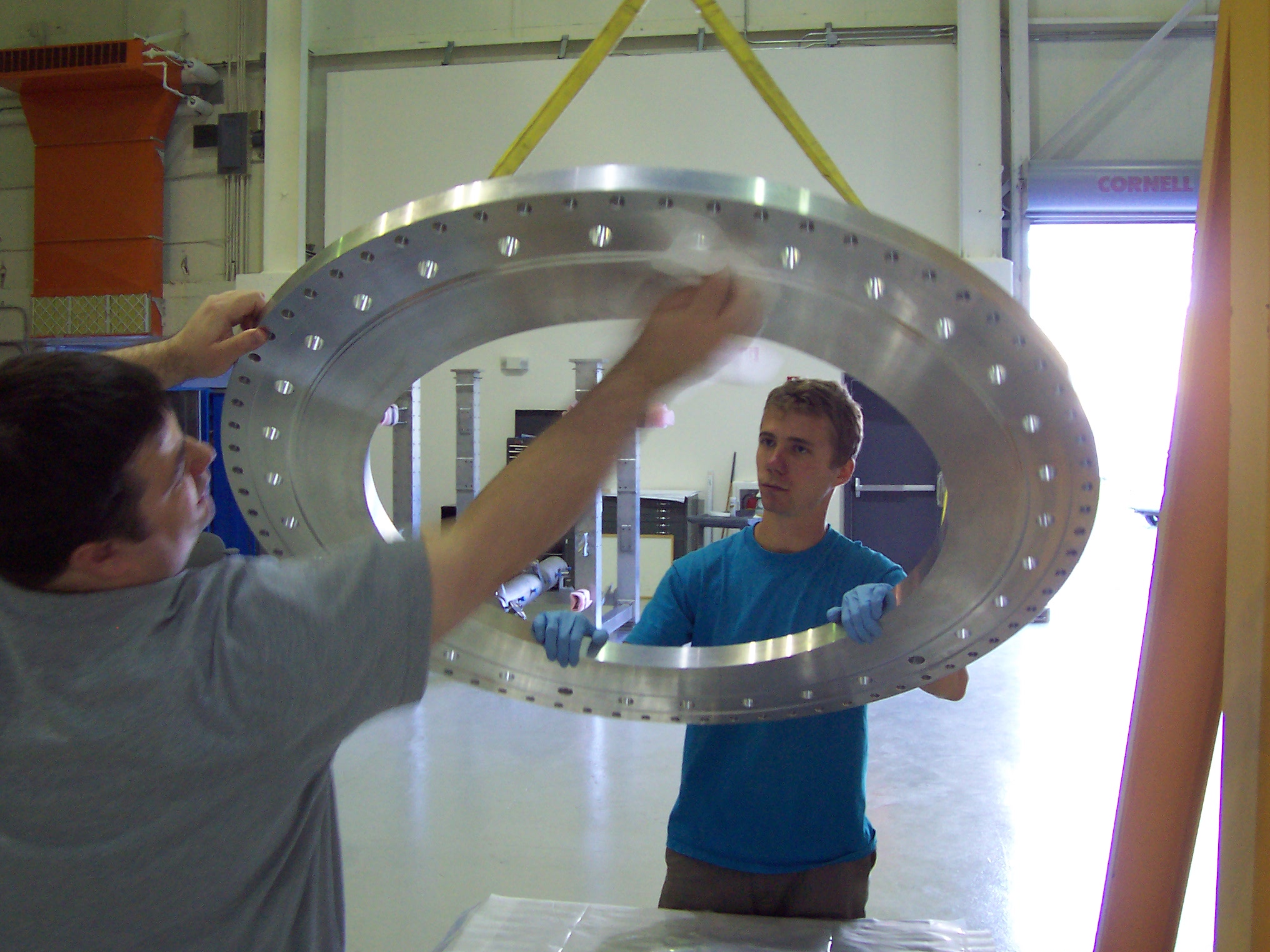
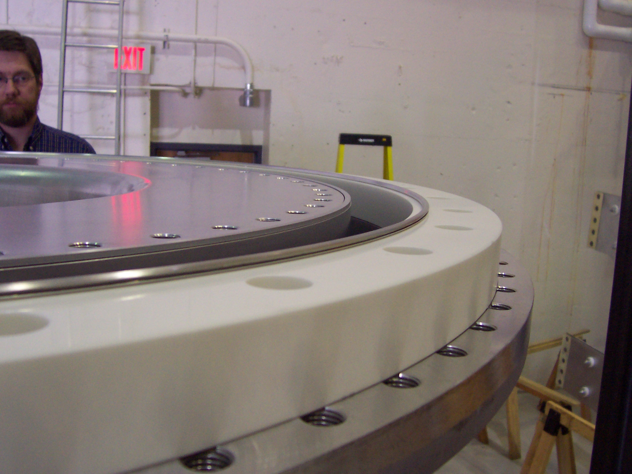
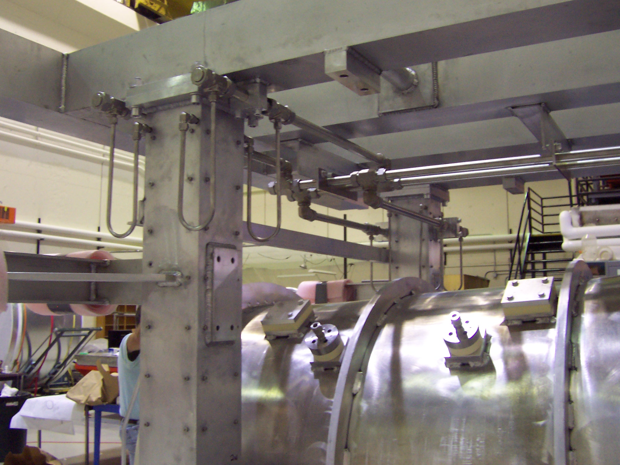
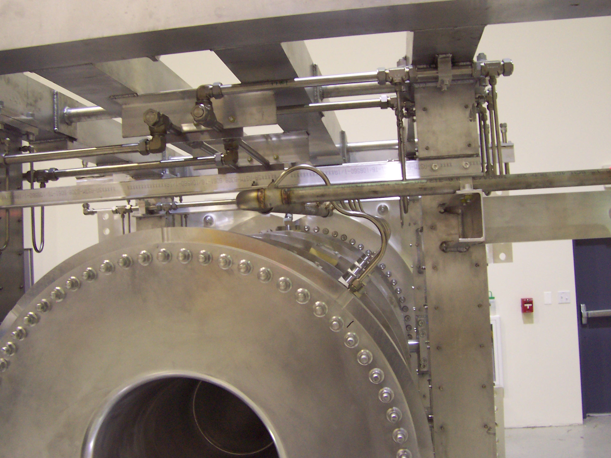
The pictures above show the beginning of the assembly of the supply and return cooling pipes for the horn. The top frame and upper plumbing is being test fit because none of these things can be in place until the horn is lowered into the support frame. This picture is a close-up of the dielectric connection between the aluminum horn and the stainless steel water piping. Atsuko Ichikawa-san of Kyoto University came up with this design concept. The ceramic is sealed on one side to the stainless with a Helicoflex seal and on the aluminum side with an EVAC diamond cross-section aluminum seal. There are bolts hidden in the ceramic that connect the ceramic to the stainless steel. (You can just see the ends of the bolts sticking out of their tapped holes in the SS flange.) The counterbored holes visible in the flange are for aluminum bolts that connect the assembled flange to the outer conductor of the horn. The ceramic's purpose is two-fold. It electrically isolates the water system from the voltage of the outer conductor of the horn and it prevents galvanic corrosion between the water system and horn outer conductor. This fixture allows us to gently clamp and lift the ceramic ring to place it on the outer conductor mounted on the rotating fixture.
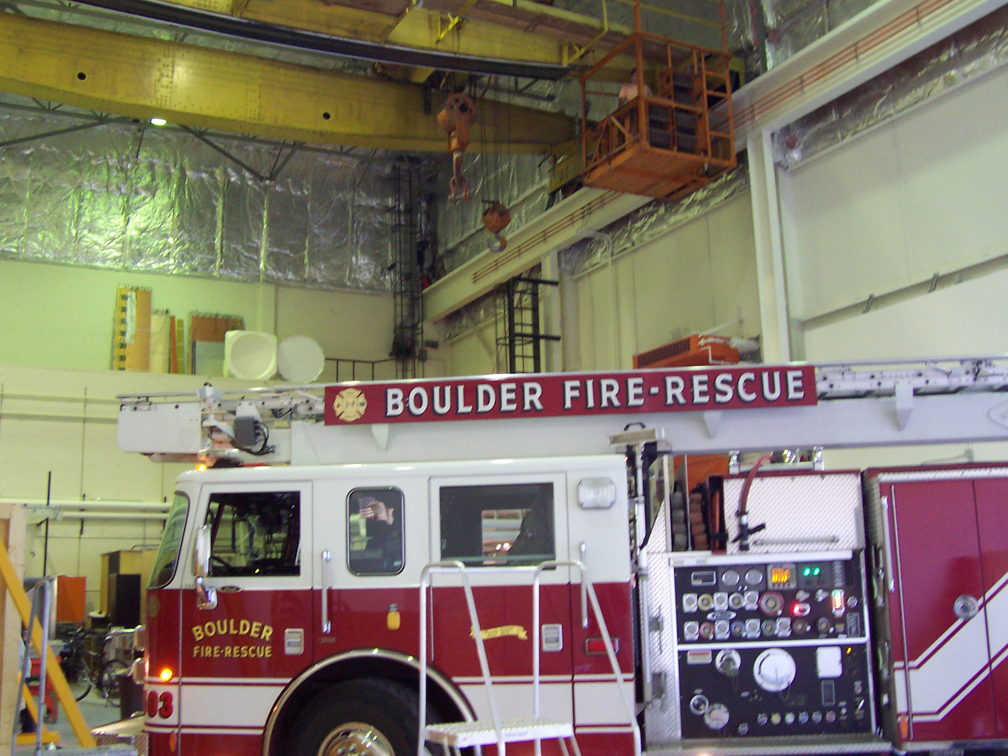
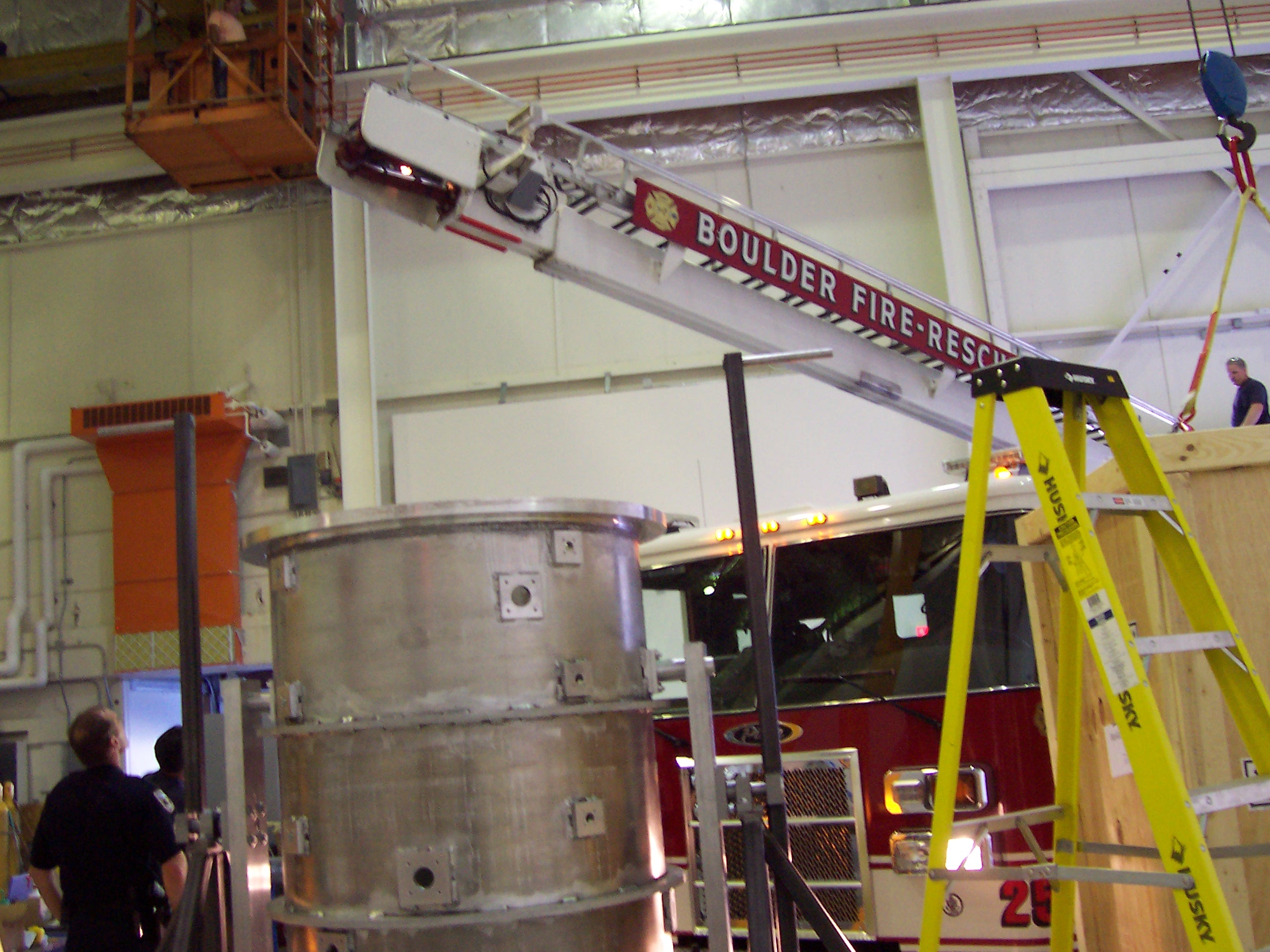
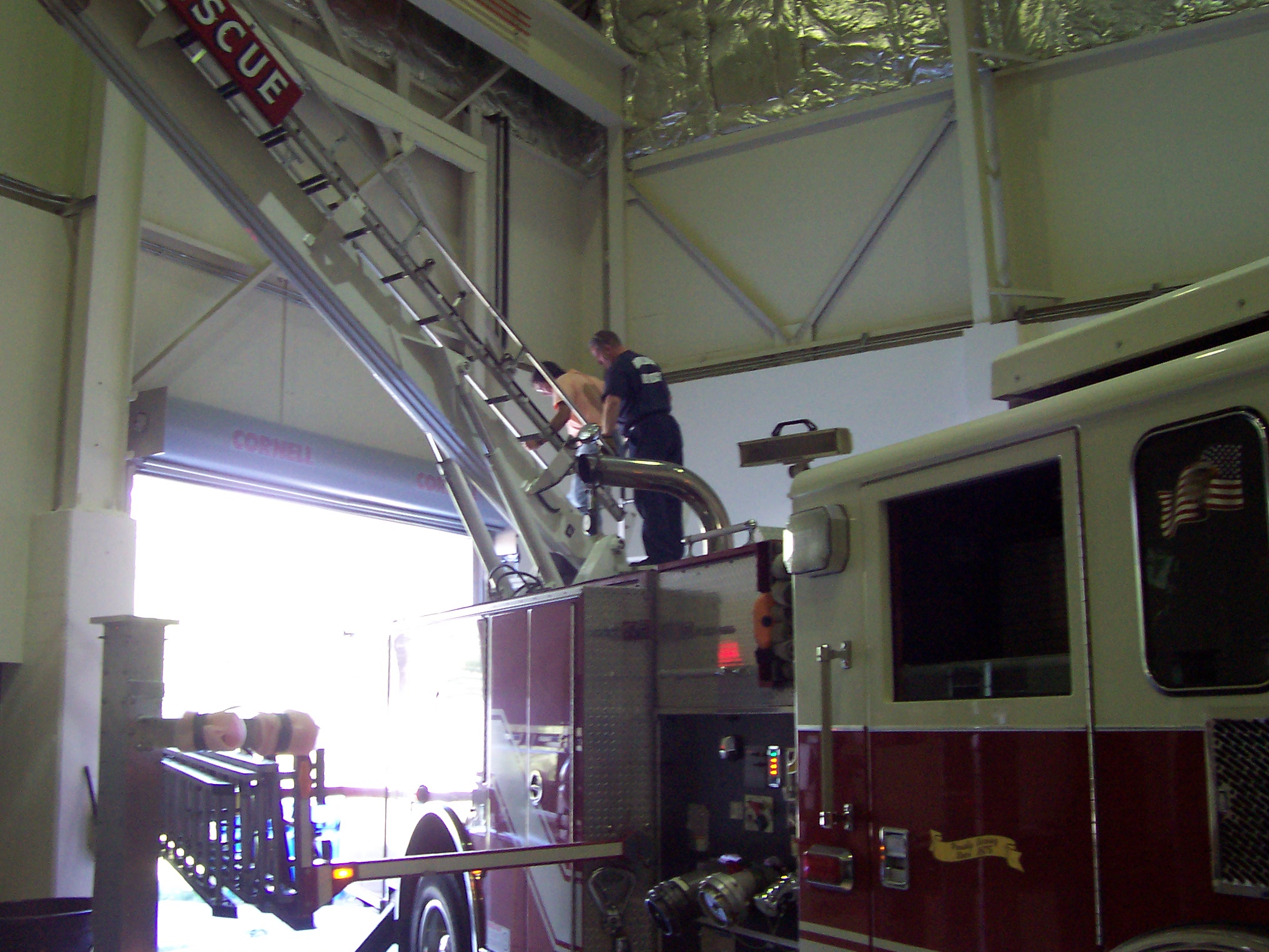
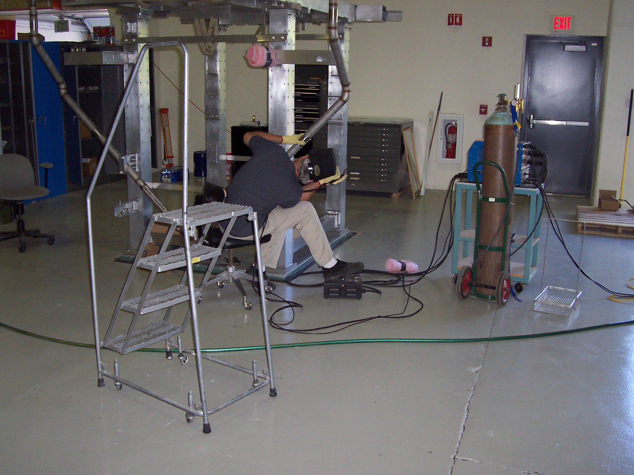
These pictures show our chief technician Eric Erdos being rescued by the Boulder Fire Department. The crane bridge motion failed which prevented Eric from being able to climb down from the crane using the ladder mounted on the wall. An exciting afternoon was had by all!
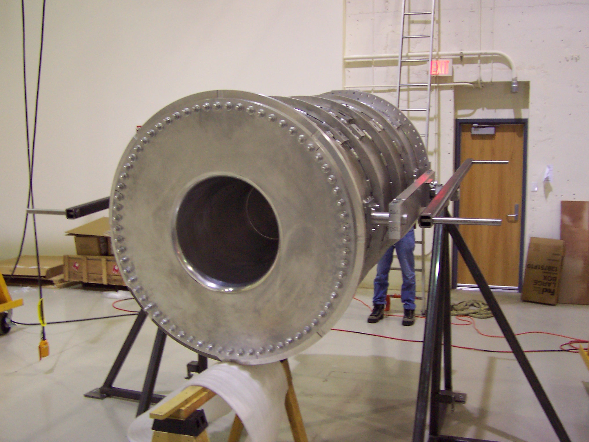
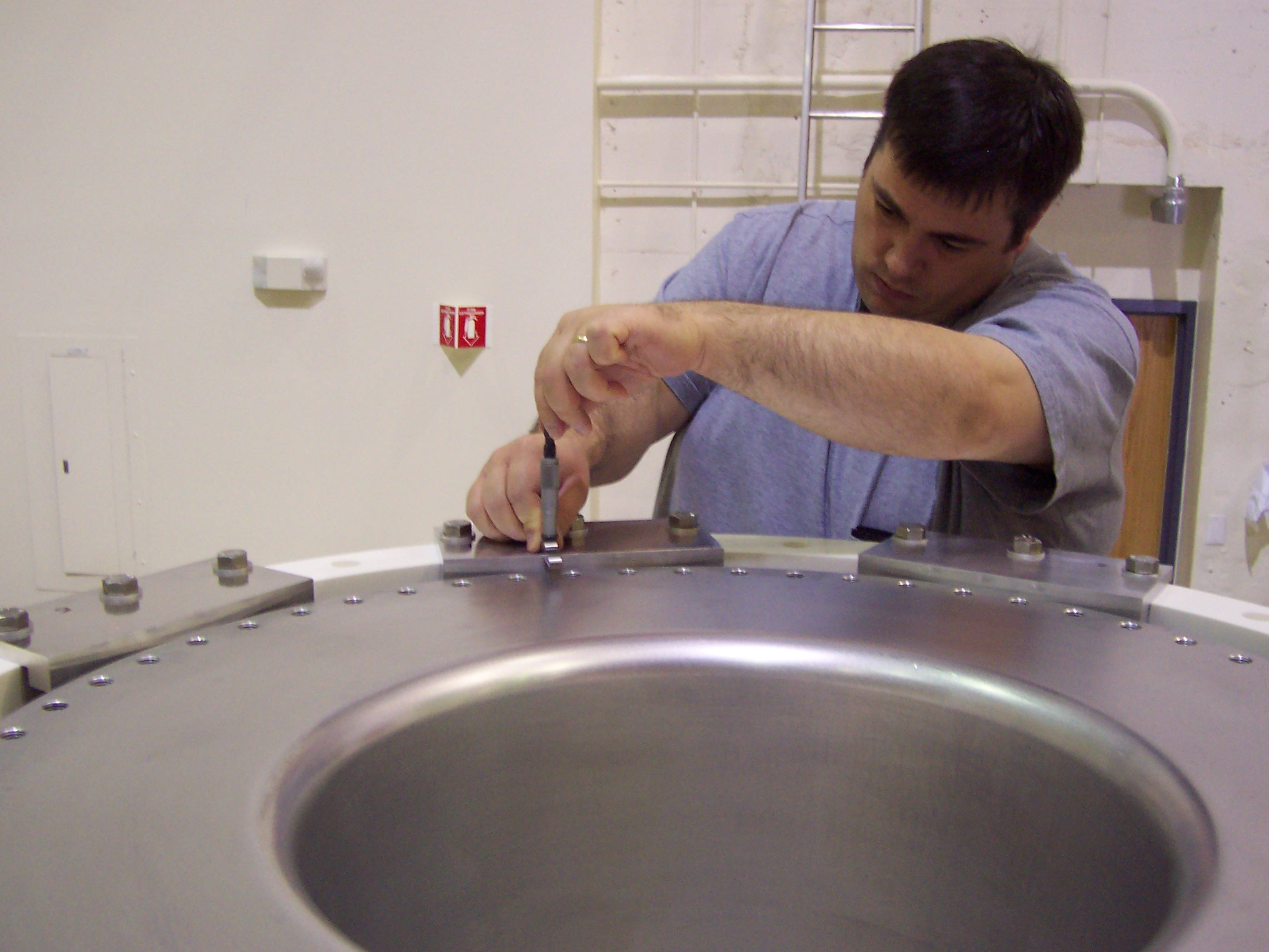
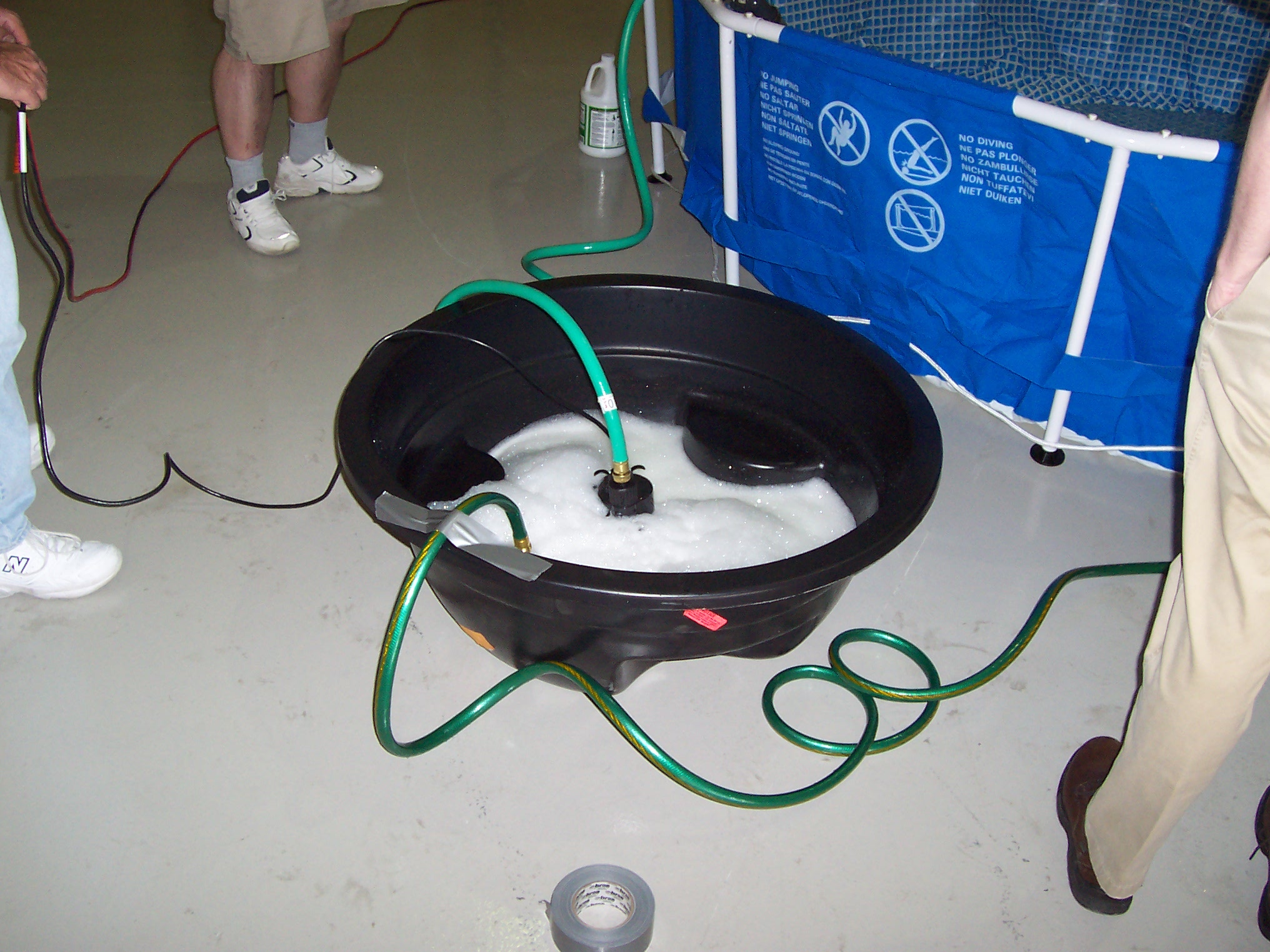
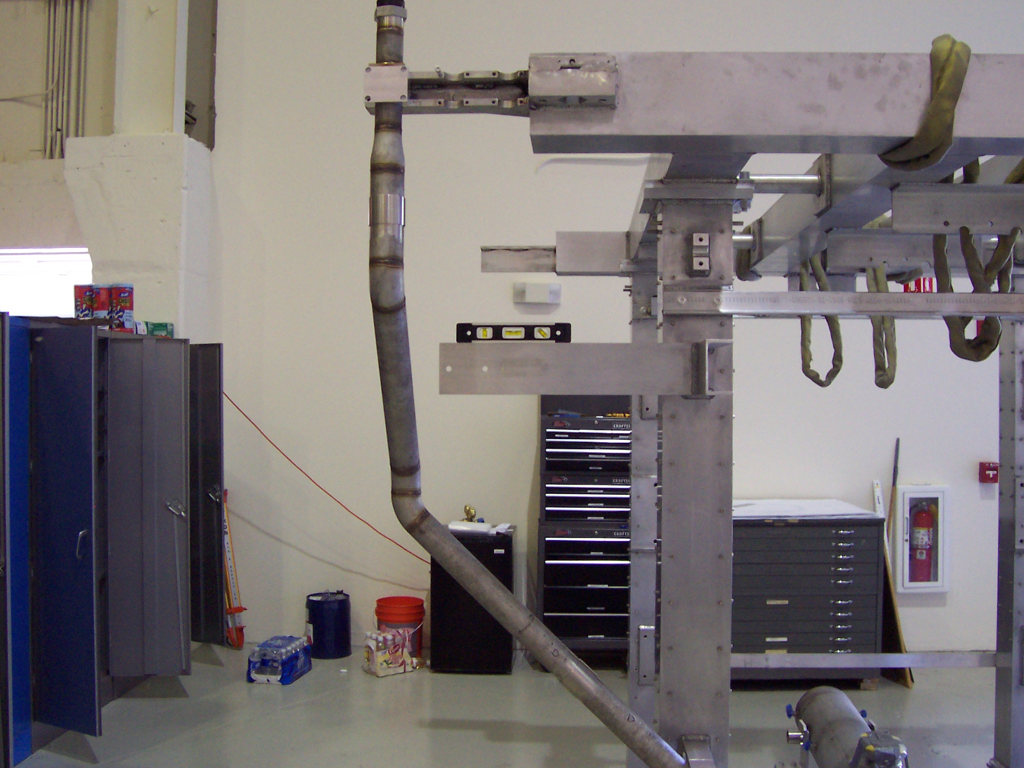
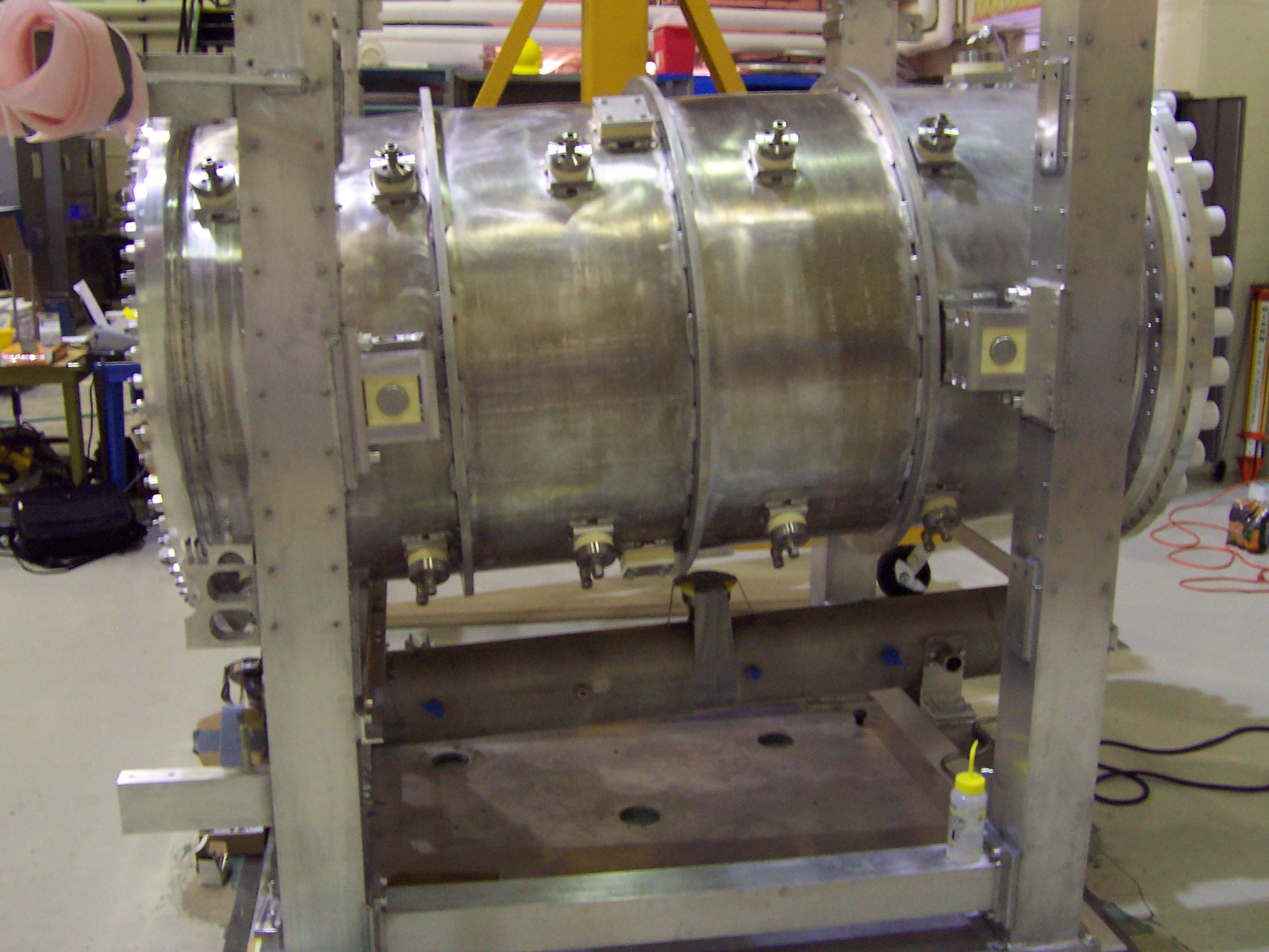
These pictures show the inner conductor (IC) assembled into the outer conductor and restrained by fixturing blocks so the IC doesn't bend when the assembly is rotated or the ceramic ring fall off. The reason the ceramic ring has to be rotated to the down position is because due to welding you don't really know how long the inner conductor is with respect to the outer conductor. Measurements between the ceramic ring and the inner conductor must be taken with the ceramic ring in the top position and the bottom position so the length of the inner conductor can be averaged. (Gravity causes it to stretch or compress depending on which position it is in.) Once the average difference is determined, a pocket can be machined in the upstream end flange that allows the end flange to be bolted to both the inner and outer conductors without stretching or compressing the inner conductor. Crane handling, inspecting and cleaning of the Upstream end flange that electrically connects the inner conductor to the stripline and mechanically to the outer conductor. We purchased a child's swimming pool and a sump-pump to clean our larger parts. It's very important to make sure there are no small chips in the water supply lines as they can clog the tiny orifices in the spray nozzles inside the horn. Tracy is a machinist and welder in the CU Physics shop and he expertly corrected some problems with our drain lines. The actual "standard" 45 degree elbows that were bought for the drain line did not match the CAD models of the fitting causing problems during fit up. The ceramic ring has a Helicoflex seal laid on it and the inner conductor has a custom square cross-section seal in its o-ring groove in preparation for lowering the Upstream end flange and making the horn water-tight. The square cross-section seal is my custom design that is made from annealed almost pure aluminum and is intended to be a water seal and carry the full current of the horn.
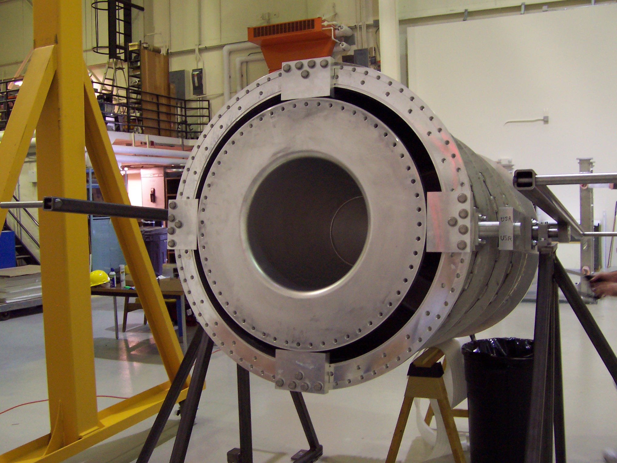
These pictures show the horn finally placed in the support frame. Stripline and water piping assembly can now be completed. The stripline "ears" are connected to the horn. The side portions of the striplines were pre-assembled and shipped separately because together they were more fragile and did not fit inside the shipping box.
The remaining work was to assemble the manifold that provides water for the frame cooling system. Every Swagelok fitting was torqued and checked with a gage. The support frame had an auxiliary shipping frame bolted within it to carry the weight of the horn. This protected the ceramic block supports during transportation. The final step was to assemble the shipping crate around the horn for its flight to Japan.
Back to the Bartoszek Engineering T2K Main Page
Back to the Bartoszek Engineering Projects Page
Back to the Bartoszek Engineering Home Page
|


