|
The T2K Horn 1 Page
This page shows the photos of the final design of the T2K Horn 1. Bartoszek Engineering worked closely with Atsuko Ichikawa and other staff of KEK to develop the design of the first horn in the three horn system of T2K.
Click on any of the thumbnails to get an enlarged view. You are welcome to download any of the images. If they are used for other than private viewing, credit to the T2K collaboration and Bartoszek Engineering would be appreciated.
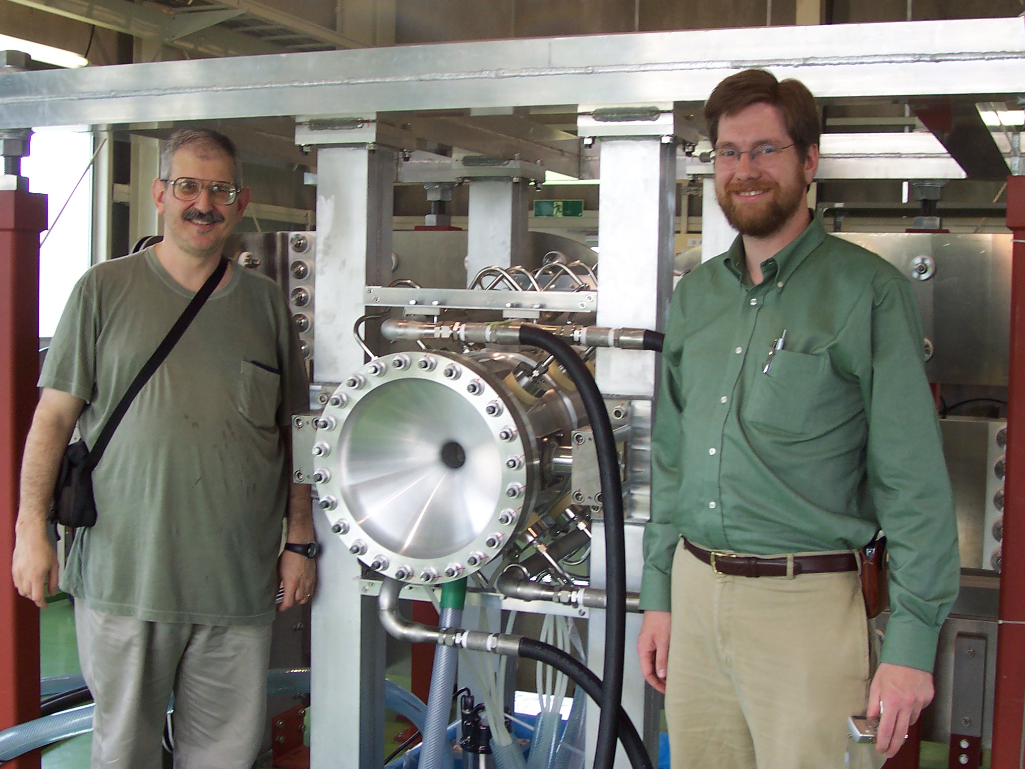
Ichikawa-san, Eric Zimmerman and I pose before Horn 1 as it enters its first pulse tests up to 250 kiloAmps. Horn 1 performed flawlessly during testing.
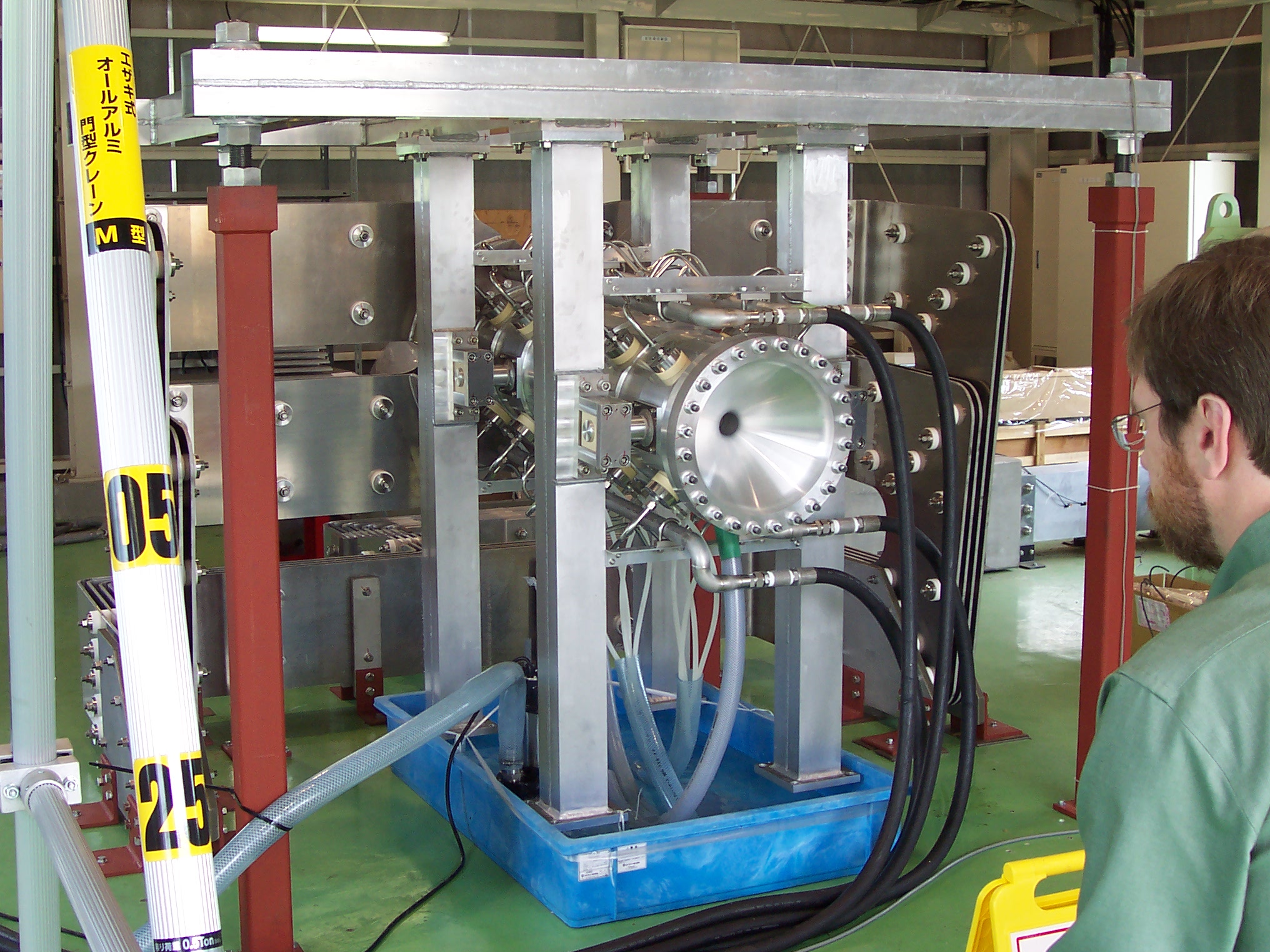
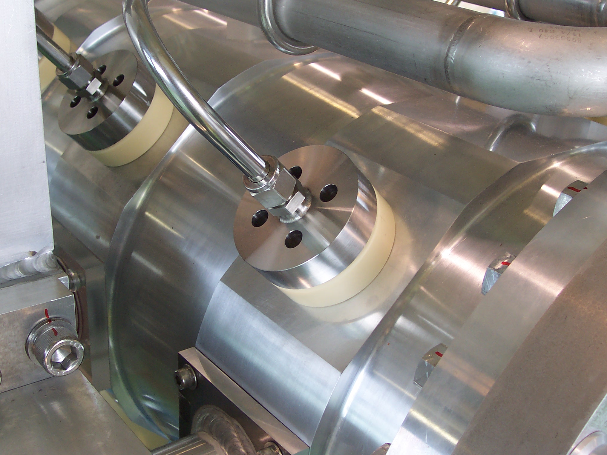
Horn 1 stripline details
Horn 1 tested a new design of stripline that BE proposed. It is as wide as it is, especially for horns 2 and 3, to reduce radiation heating of the side panels of stripline plate. The pulse is relatively long, >5 msec, so the voltage is low, ~600V. One of the lessons I took away from the testing of horn 1 is that you can get away with a lot of things in low voltage striplines that you cannot in high voltage striplines such as MiniBooNE's. Corona is not an issue in low voltage striplines.
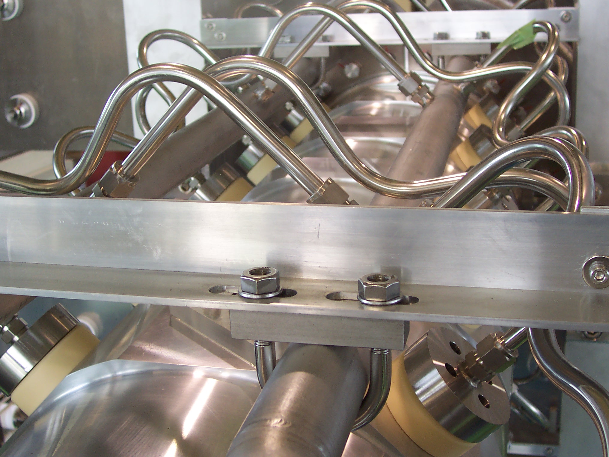
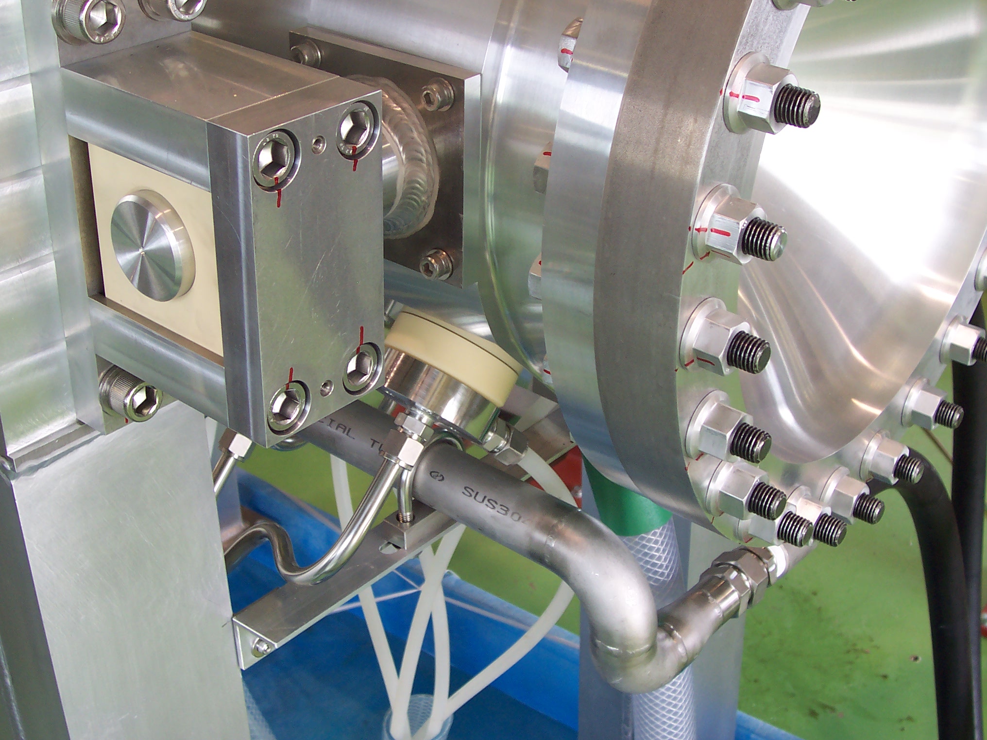
Horn 1 water cooling details
Ichikawa-san is the inventor of this style of water penetration to the horn. The problem in typical horns is that water systems are always made of stainless steel. Horns are always made from aluminum. To make a water-tight connection between stainless and aluminum you must use a dielectric material between the two metals, or the aluminum will sacrifice itself galvanically to the stainless. The first MiniBooNE horn failed because of galvanic corrosion of an aluminum seal against a stainless steel flange. This problem is elegantly prevented in this design by putting a piece of ceramic between the aluminum horn and the stainless water flange. The ceramic has counterbored holes in it to allow it to be bolted to the stainless flange from one side of the ceramic, and then bolted to the aluminum horn from counterbores on the opposite side of the ceramic. The water seal is done with Helicoflex seals between the metal and ceramic surfaces. We also incorporated what NuMI learned about over-constrained water supply tubes and put bends in our tubes to allow for flexibility. The third picture also shows the auxiliary drain tubes that prevent water from stagnating around the bottom spray nozzles. (The plastic tubes were temporary for testing only.)
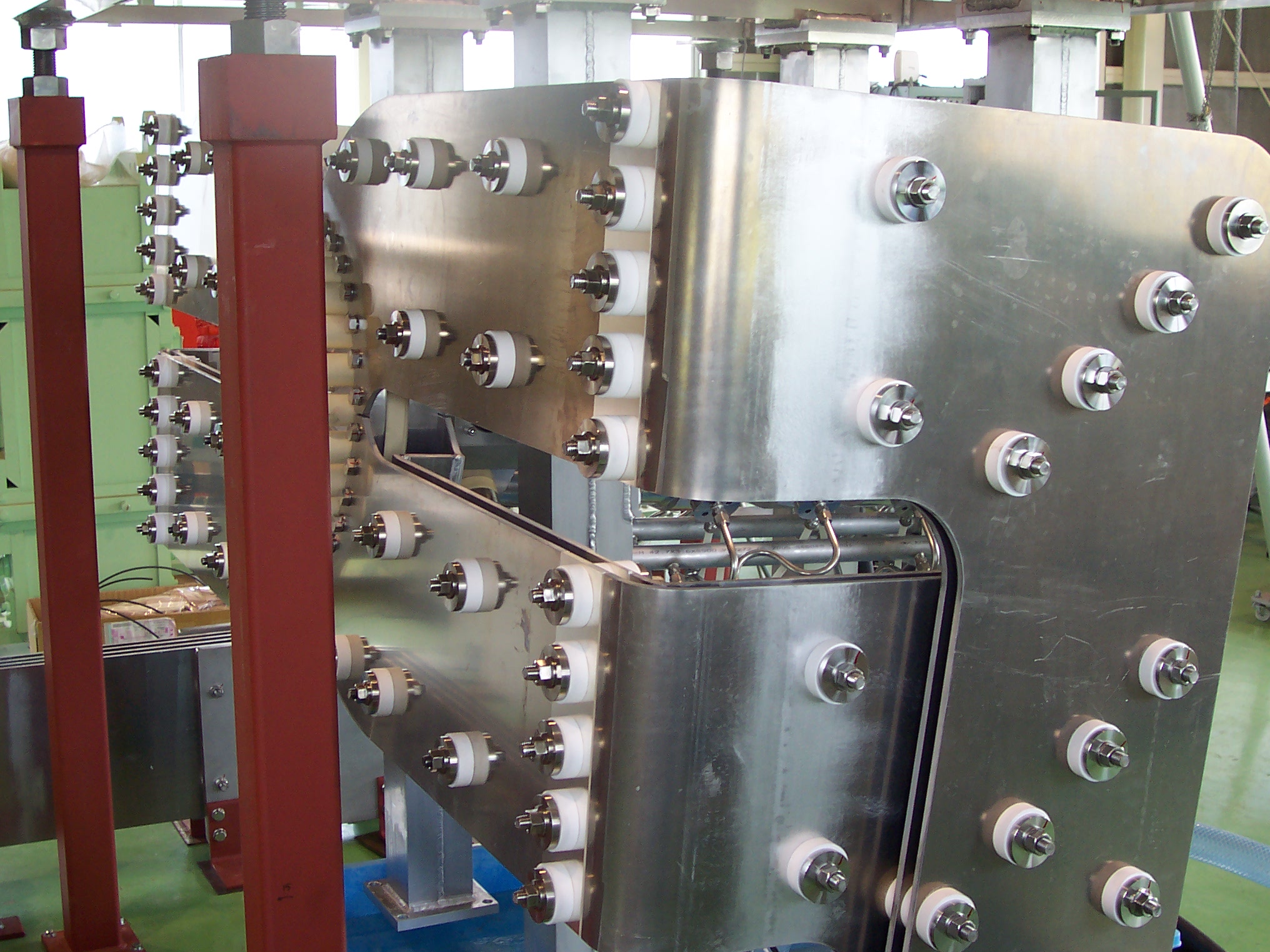
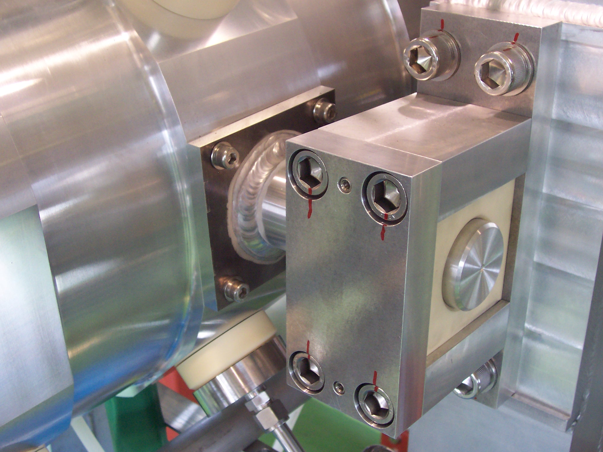
Horn 1 electrically isolating structural support details
Horns need to be electrically isolated from their support structures. BE proposed this design of supporting the horns on aluminum pins that are close fits in holes in ceramic blocks. The upstream pair of ceramic blocks are fixed in their aluminum housings. The downstream pair of blocks is allowed to float in the beam direction to allow for assembly tolerances and thermal expansion movement. This design was used for all three horns.
Back to the Bartoszek Engineering T2K Main Page
Back to the Bartoszek Engineering Projects Page
Back to the Bartoszek Engineering Home Page
|