|
Design of the FINeSSE LAr TPC prototype Work done up to 3/23/05
These pictures are renderings of the solid model BE has created of the FINeSSE Liquid Argon Time Projection Chamber (TPC) prototype to be built at Yale in 2005. The page is currently under construction and will be added to as the design progresses.
Click on any of the thumbnails to get an enlarged view. You are welcome to download any of the images. If they are used for other than private viewing, credit to Bartoszek Engineering would be appreciated.
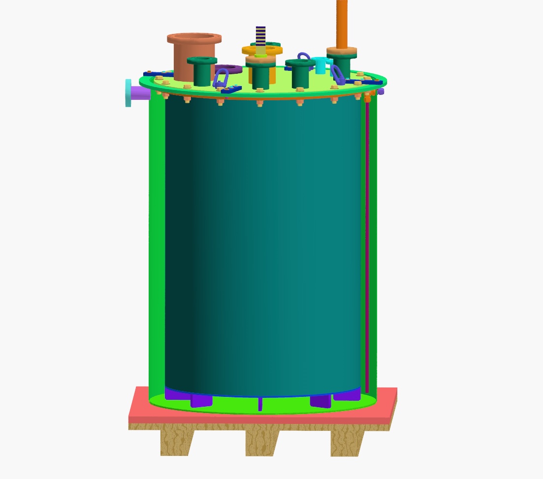
This picture shows the scale of the TPC prototype. A number of feed-throughs and ports have been defined and placed on the top flange. This design follows similar prototypes developed by the ICARUS collaboration in Europe, as well as drawing on expertise from the FLARE collaboration at Fermilab. The pink plate between the plywood and the external bath is a building insulating foam such as those available at any home center. The insulation surrounding the external bath stainless vessel is not shown. What is conceived is something like the gray flexible insulation with adhesive that is used for hot water pipes, but in much larger sheets. A plywood box can be constructed around the external bath and insulating pellets can be placed in between the external bath and the plywood to increase the total insulation of the bath. One concern is the amount of time it will take to form ice from humidity all over the external bath. While ice is an insulator of sorts, it could reduce the insulating value of any pellets. The surrounding plywood box is also not shown but would be similar to previously shown designs.
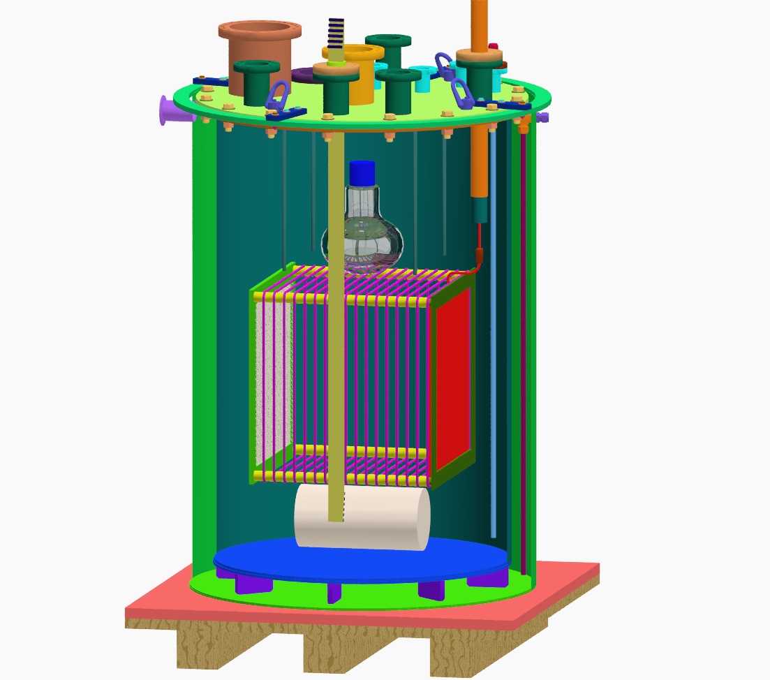
This shows a cutaway of the external bath cylinder to reveal the inner TPC vessel. Regular liquid argon is used in the annular space between the inner and outer stainless vessels to cool the inner vessel. Once the inner vessel, under vacuum, has been cooled to LAr temperature, ultra-pure liquid argon is introduced to the inner vessel.
This picture cuts away the cylindrical wall of the inner TPC vessel to expose the wire chambers and components which all hang from the lid of the TPC vessel. The white cylider at the bottom is a place-holder for the purity monitor. Note that fill tubes for both the inner and outer vessels have been designed.
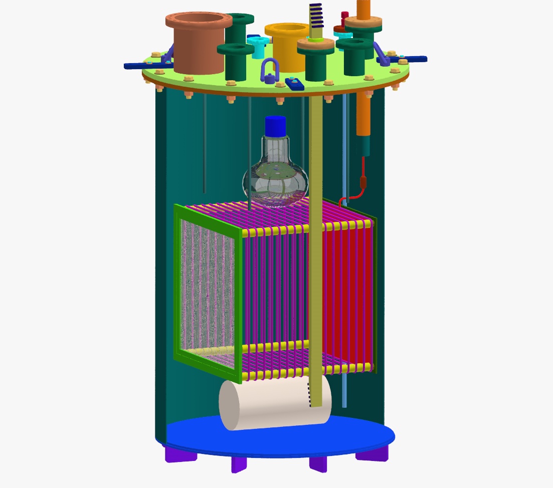
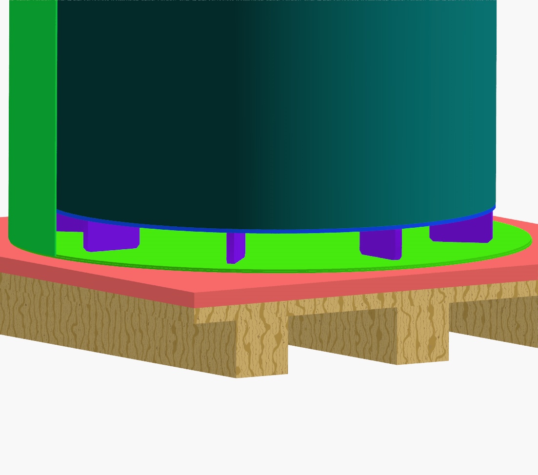
This view is a rendering of the TPC vessel cutaway without the external bath. Notice that the tank has eight new plates at the bottom arrayed radially to allow liquid argon to get to the bottom face of the TPC vessel. The feet plates will be chamfered and should offer enough surface area that the contact pressure will not be too great when the vessel is standing on the floor. These feet are welded to the bottom plate and this was thought to be safer and more convenient than the earlier wooden blocks inside the external bath.
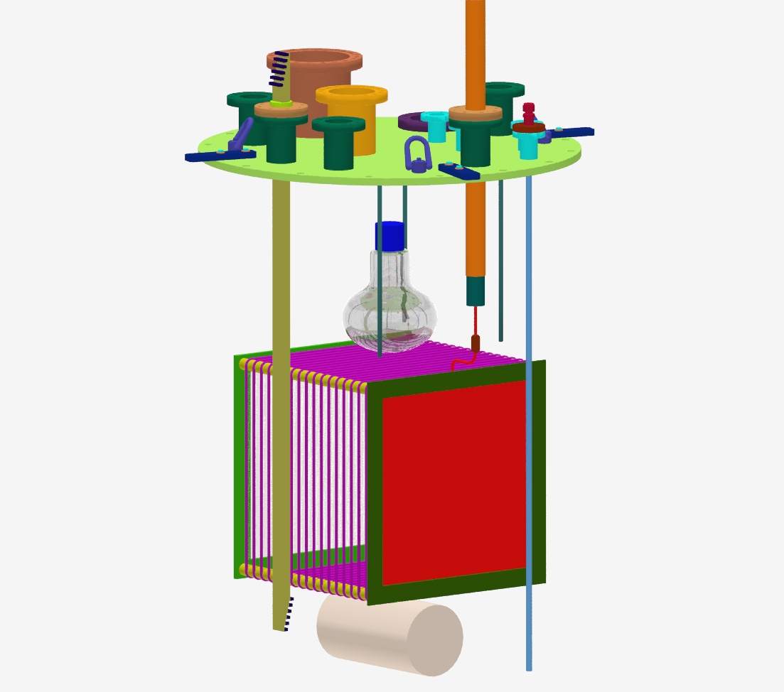
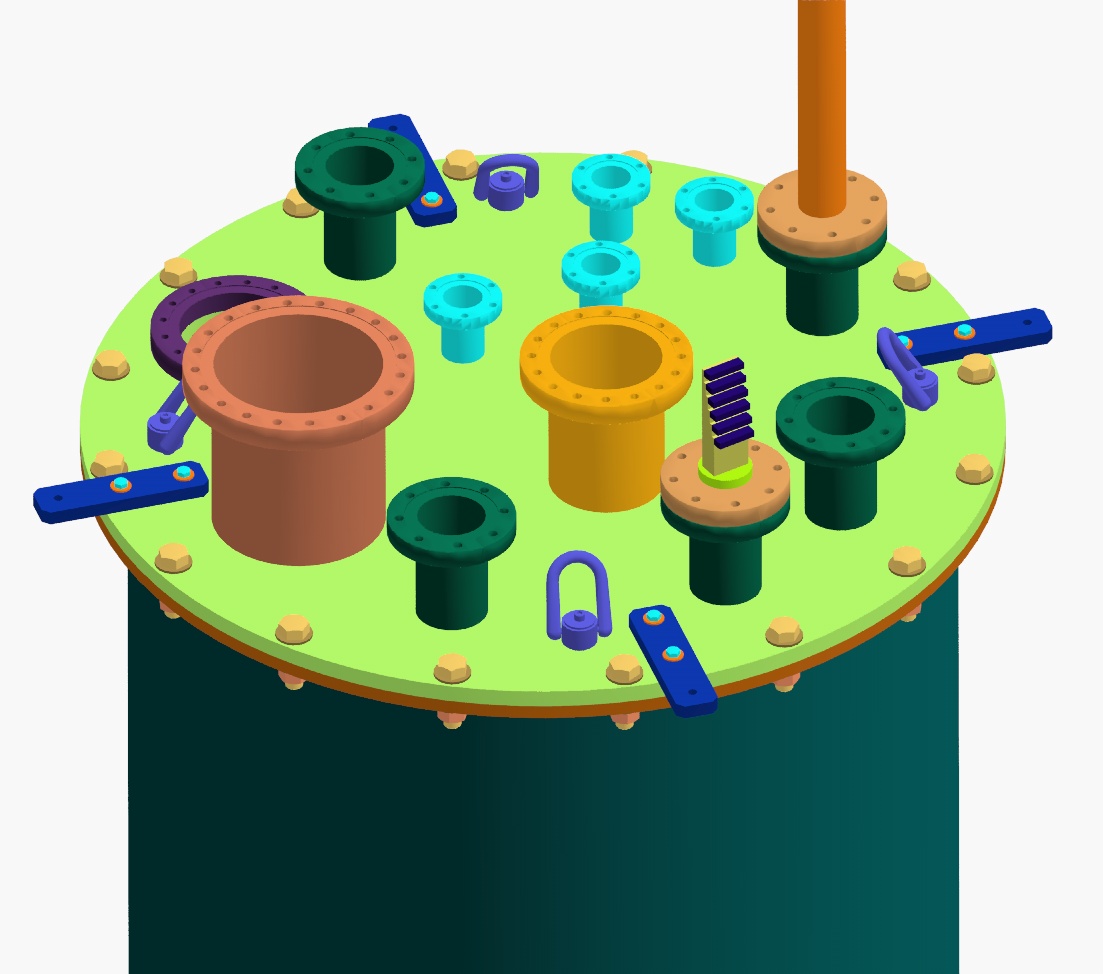
This picture shows the components that are supported by the top flange of the inner vessel. Not all the connections have been designed yet.
This is a close-up of the top flange of the TPC. The four bars extending over the edge of the flange connect the inner vessel to the top flange of the external bath. If these bars were not in place, when the inner vessel is under vacuum and empty of LAr it would float in the external bath as that is filled with liquid argon. The brackets are designed with enough safety factor that this will not be a problem as long as the bolts are tight. Notice that the number of bolts to seal the top flange to the barrel has been reduced to 16 (from 52), making it much easier to make and break this connection to modify the inner components. The original vessel was conceived to be a pressure vessel capable of withstanding several atmospheres of pressure. Now, the TPC will be run just a couple of psi above atmospheric pressure. It is primarily designed as a vacuum vessel.
A close-up of the new feet plates.
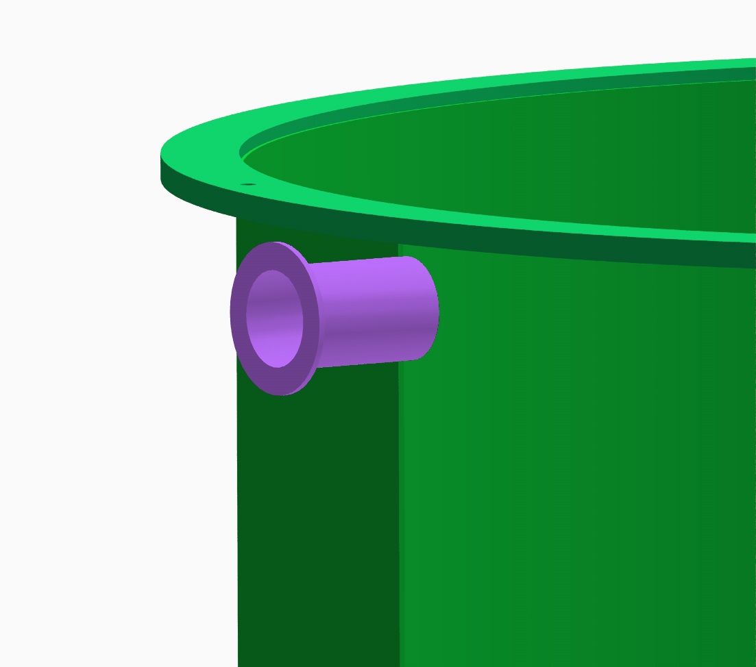
This is an NW50 half-nipple welded to the external bath barrel. This port is used to vent boiled-off argon to a window and outside.
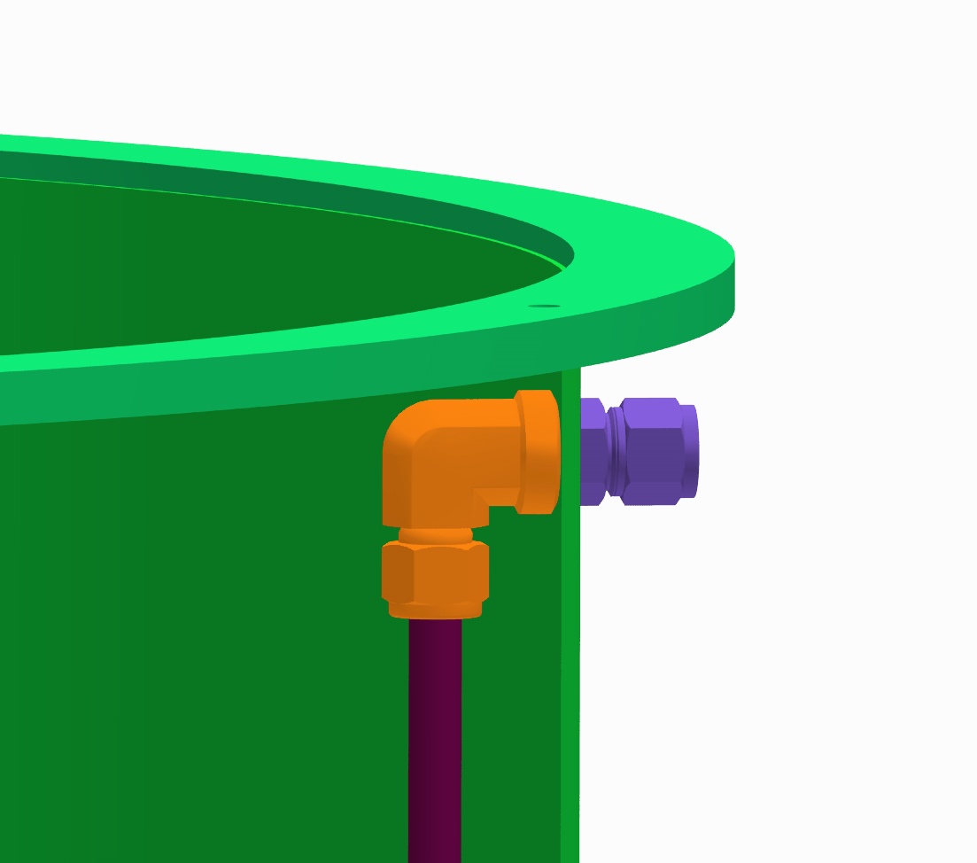
This is a close-up of the liquid argon fill feed-through for the external bath. The only feature required on the external bath barrel is a .875" diameter hole. The inner fitting is a Swagelok female pipe thread elbow. The external fitting is a male pipe thread tube connector. Together, they form a bulkhead feed-through that makes a 90 degree bend immediately inside the external bath. (I thought this was pretty clever since you can't buy an elbow-bulkhead fitting.) This fill pipe was originally directly opposite the vent fitting but had to be rotated by 11.25 degrees to avoid colliding with bolts from the inner vessel's vacuum flange.
Back to the FINeSSE Main Page Page
Back to the Bartoszek Engineering Projects Page
Back to the Bartoszek Engineering Home Page
|