Booster Collimators prior to 1/03These photos show the existing Booster Collimators as they were in the Booster prior to removal in January of '03. As can be seen, there are many more features on the real things than are shown in the solid model on the conceptual design pages. These are included as a reference for the drive trains which are slightly different than their manufacturing drawings. Click on any of the thumbnails to get an enlarged view. You are welcome to download any of the images. If they are used for other than private viewing, credit to Bartoszek Engineering would be appreciated.
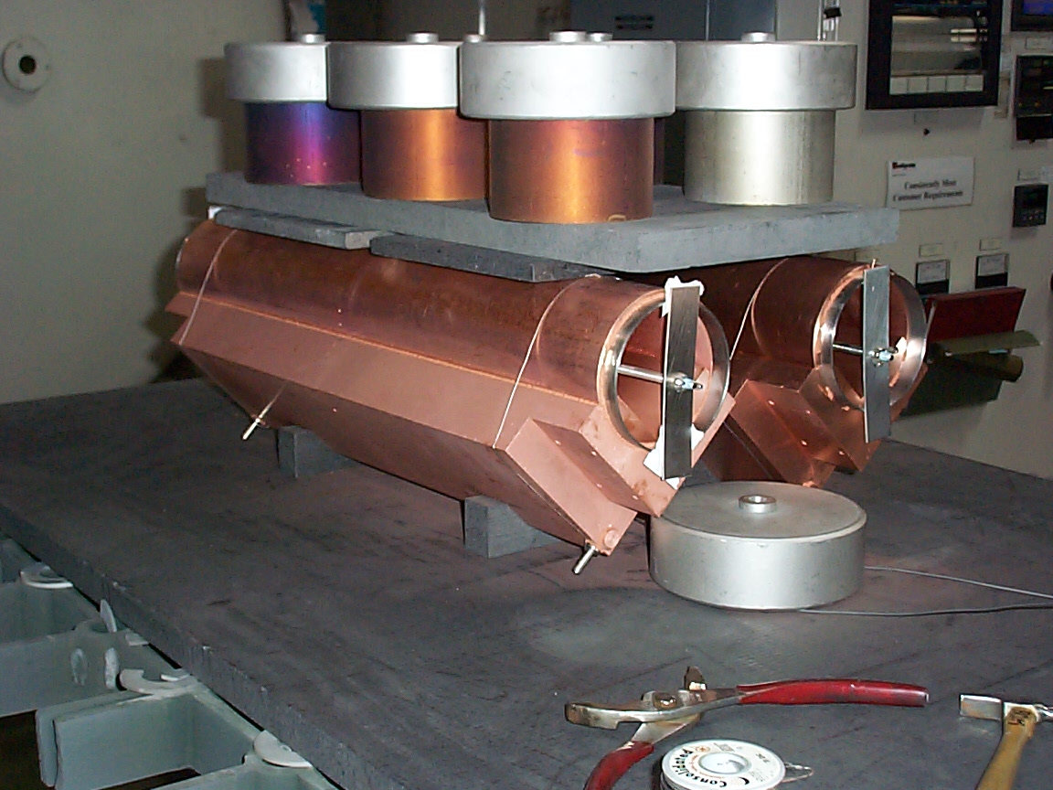
Collimators being prepped for oven brazing
This picture shows two collimators being prepared for oven brazing to make a vacuum tight assembly. It was included to show the ports for water cooling. There are a number of unresolved issues associated with water cooling, such as routing the plumbing to allow for the motion of the collimator without stressing the tubes. Are we allowed to route LCW directly through the collimator dumping radioactive water into the LCW system? If not, is there a plan to make new RAW systems for the collimators? Is water cooling absolutely necessary?
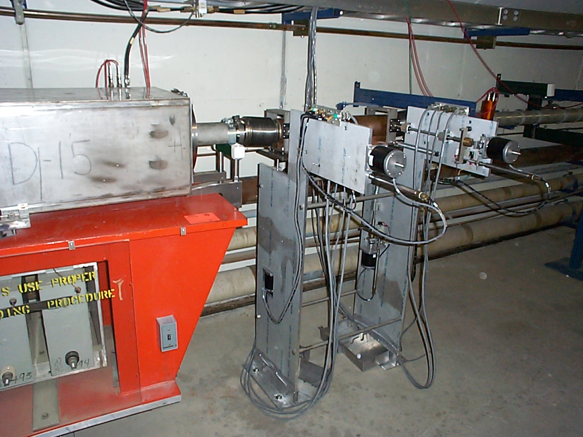
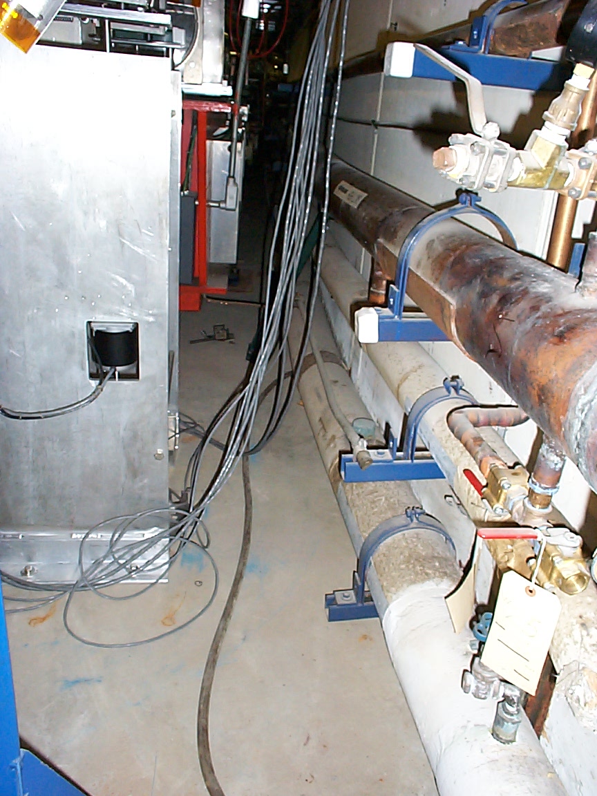
Overview of the three collimators in the Booster
The picture on the left shows the collimator furthest from the entrance to the Booster. The middle one is the middle collimator, and the right one is the collimator closest to the Booster entrance.
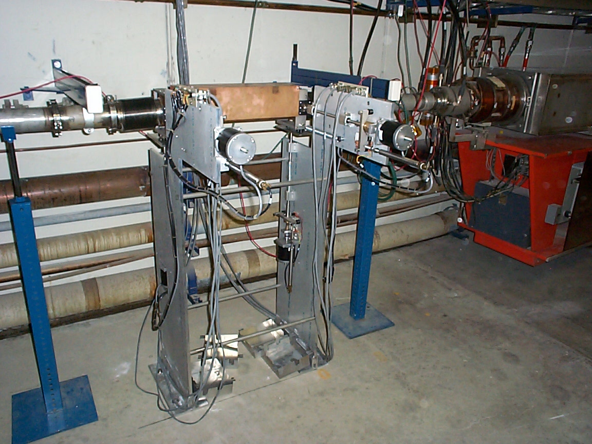
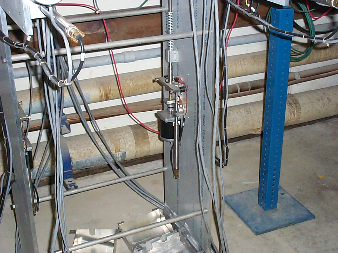
Different views of the vertical drive mechanism
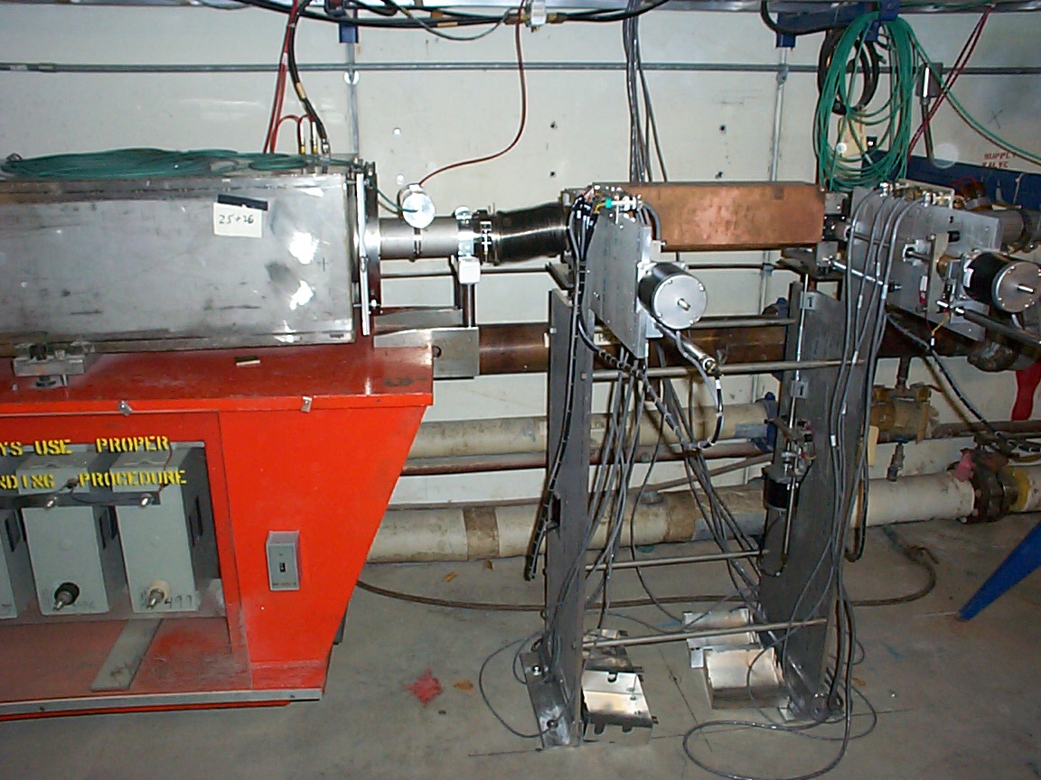
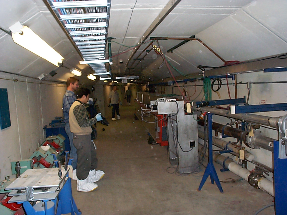
View looking upstream in the Booster tunnel
This picture shows what the tunnel area looks like around the collimators. Back to the Booster Collimator Shielding Main Menu Back to the Bartoszek Engineering Home Page |